TAWP tool is pretty good at taking milling machines apart, not so much at putting them back together again. That makes two that I know of... He should have paid you to get it into usable condition! I'm really glad you heard about it first, because I might have been tempted to try to put it in my shop, where there is no room for it.
 
After too long, i have fired this project up again.
since the last post, i have done a bunch of scraping on the lil beast, trying to bring her back to square.
it has been challenging.
 
Last edited:
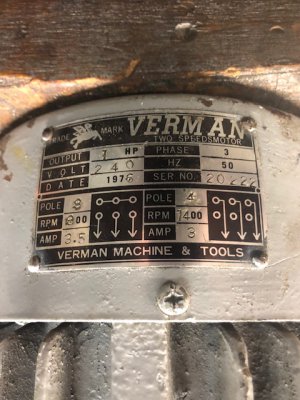
i have reassembled and reinstalled the vertical spindle, and i started rebuilding the 3 phase Verman 2 speed motor
as follows:
IMG_4302.jpg

even though the bearing are almost 40 years old, the bearings sounded very good.
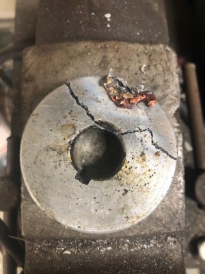
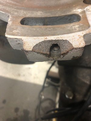
the motor suffered slight damage to the mounting flange.
there was a handle that is used to manually set the drive belt tension, a small piece of cast iron spalled off for unknown reasons.
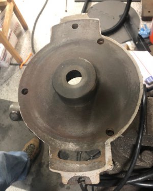
i removed the end plate and disassembled the motor for rebuild.
IMG_4304.jpg IMG_4303.jpg

luckily i had 2 of the 6204-2RS shaft end bearings and the 6203-2RS fan end bearings here at home.
bearing removal and replacement was uneventful.
i did find it funny that the spindle side bearings were open bearings, the fan end had 1 metal shield , there was no provision for lubrication for either set of bearings, so replacement with -2RS bearings was a no brainer.
after pushing the new bearings on the rotor, i went to the repair of the mount flange tension adjuster

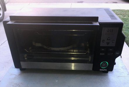
i used my $12 shop oven to preheat the casting to 350°F for an hour

IMG_4306.jpg

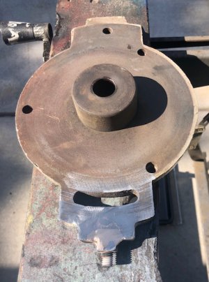
i made a stud from 3/8" all thread x 2" and installed a square nut for added support
i brazed the works up with silicon bronze and resurfaced the affected area to flat again.

before: IMG_4304.jpg

after: IMG_4308.jpg

before disassembly, I tested the motor and hooked a VFD to it , have a look at the video if you have interest:


there is plenty more to come, STAY TUNED!!!!!!
 
Last edited:
after making sure the motor runs, i started thinking of the next step...
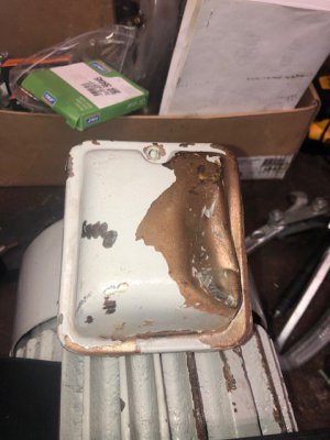
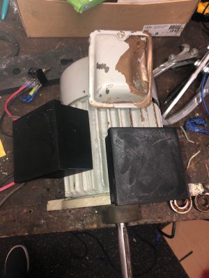
the electrical enclosure was clobbered.

IMG_4312.jpg

i thought about straightening the cover, but designing and 3D printing a new enclosure sounded like more fun!
so i designed 2 different versions.
both have convenient snap on lids
the first version proved to be a bit cramped at only 90mm square X 30mm high
i increased the depth to 90 square X 50mm on the second model
the second model is current installed on the picture below to the left side,
the clobbered box and the first prototype added for comparison

IMG_4311.jpg.

after jumping the small hurdle of electrical enclosure, i decided to look at the step pulley next.

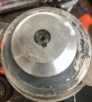
there was no provision for locking the 4 step pulley to the keyed shaft other than the friction of a distorted key.
that is the key is beveled on the end.
when the bevel meets the small radius of the key slot, when driven in, the key rises and wedges against shaft and pulley
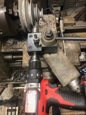
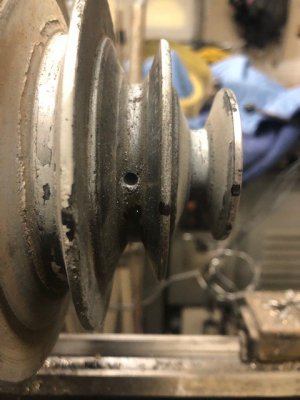
i decided to crossdrill the pulley and add a set screw for higher security
so once again, my not so famous AXA crossdrilling fixture was dusted off for service once again
https://www.hobby-machinist.com/threads/shop-made-axa-toolpost-cross-drilling-fixture.49064/

IMG_4313.jpg IMG_4314.jpg

i drilled and tapped for M6-1.0 for the set screw

pulley installation is next!!!
 
I installed the pulley,
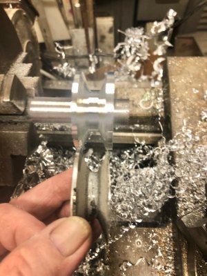
but i managed to break the smallest drive portion of the 4 step pulley in the process :bang head:
i made an attempt at repair and screwed that up too :bang head::bang head:

IMG_4317.jpg

so i did the next best thing....
i parted the broken pulley portion from the other 3 steps and installed the pulley again.
this time the 3 step pulley is retained with a M6x 1.0x10 set screw.
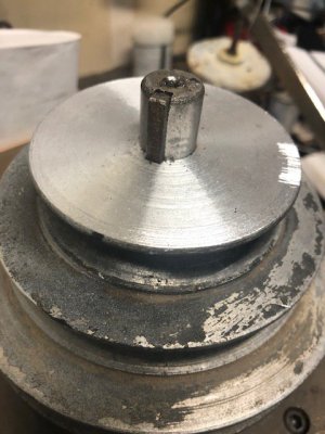
IMG_4318.jpg

i decided to reproduce the small pulley from 2.5" 6063
i drilled and bored the pulley to 17.5mm
i turned a 17.4mm mandrel , held in the 3jaw
i left a small 17.5mm step in the mandrel that i used to wedge the pulley onto the mandrel
i mounted the 2.5" slug and turned to to 2.20"
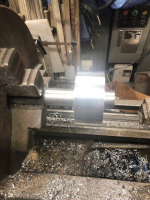
IMG_4316.jpg

i roughed out the general shape of the new pulley
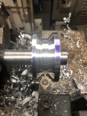
IMG_4321.jpg

there was some interesting manipulation of the toolpost angles to make the reproduced pulley match up with the OEM

i intentionally made the replacement pulley thicker,
so my heavy hands will have a harder time mangling this copy. :grin:

IMG_4322.jpg
i used my AXA crossdrilling attachment again and drilled a 5mm hole
i dismounted the new pulley and tapped for a M6x1.0 setscrew.

this brings up a hurdle...
the motor is not normal in respects to NEMA or IEC standards in regards to shaft diameter
it has a 17.5mm shaft, i don't have a 17.5mm x 3/16" broach bushing
so it's time to put up or shut up....
i took some 1018ish and whipped up a 17.4mm broach bushing slug that needs the 3/16" push broach slot.

the next hurdle presented itself...
how to hold the slug, that has 2 diameters, in a vise and have the whole top surface accessible for machining?
my first thought was to drill and bore a hunk of hex stock to accept the broach slug,
then slit the hex stock and clamp it up in a vise and be done with it.

instead, i chose an unorthodox method.
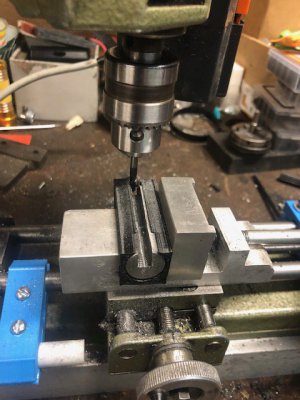
i 3D printed a vise mounted fixture to aid in the slotting of the bushing slug.
i clamped the slug fixture into the shaper vise and ground a tool 4mm wide and just over 7mm deep
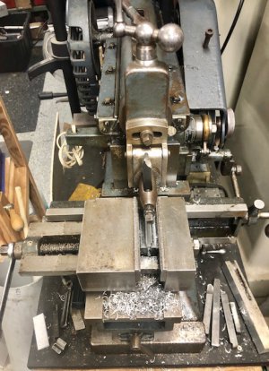
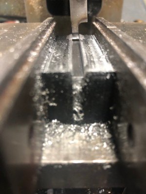
IMG_4324.jpg IMG_4323.jpg

i roughed off about .250".
i decided to go a different route to take off the next .135"

but, that will be in the next act Coming Soon!!!!!
 
After some time on the shaper, i considered another way of taking off the last .135" off.

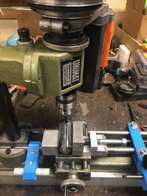
i have 2 unimat's. they are lathes as well as milling machines(as well as many other purpose built tasks),
when set up for the various modes of operation.

i mounted the partially completed broach bushing slug and 3d printed holder into the vise i constructed, on the unimat.
the mounting was precarious but with light cuts ( and a pile of razor sharp needle swarf that i'm still picking out of my fingers) it worked out!!!
i used a 4flute 3mm carbide endmill 2600 rpms to cut the rest of the broach bushing slot.
i don't have endmill holders yet for the unimat, so the endmill was held in the drill chuck

IMG_4327.jpg IMG_4328.jpg

i was able to complete the bushing slot in a couple hours.
here are the pictures!

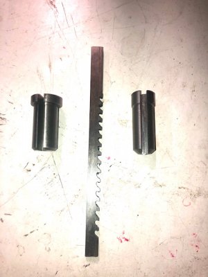
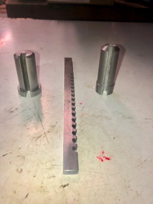
to the left is a stock 3/4" dumont broach bushing, my 17.5mm x 3/16" to the right, in both pictures below.

IMG_4329.jpg IMG_4330.jpg

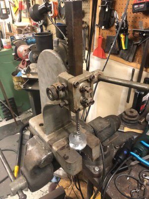
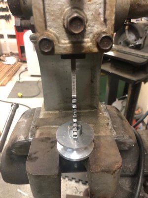
i mounted the broach bushing, push broach, and the pulley into my vintage arbor press, mounted the arbor press in my vise, and oiled the broach and bushing pushed the broach through the pulley

IMG_4333.jpg IMG_4334.jpg

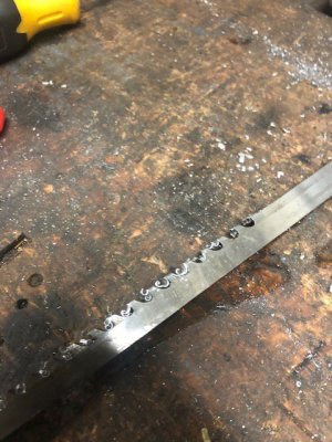
i added a .015" thick shim to the bushing and pushed the broach through again to get the end dimension.
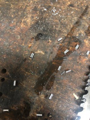
her are the little chips formed by the push broach

IMG_4335.jpg IMG_4336.jpg

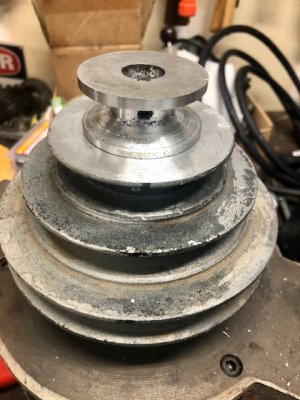
i tapped the newly formed pulley to M6x1.0, and installed the pulley on the shaft, retaining it with a shortened set screw


Below the completed pulley attached to the motor shaft
IMG_4337.jpg IMG_4338.jpg


with a little will, a little skill, some tools and some time- almost anything can be worked around.

if you take nothing else from this thread,
believe that the end result is achievable and nothing can stop you- you will achieve any goal you may set for yourself.


as always, thanks for reading!

much more to come !!!!!
 
i have come to a point where i'll be assembling more of the milling machine,
to make room to assemble even more of the machine!

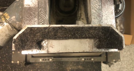
i wanted to take a moment to talk about felt wipers.....
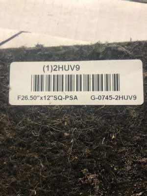
i needed some 1/2" thick material and started searching my normal places.
i found some excellent felt, on the cheap (i got 3 for $19- shipped :grin:)

for the uninitiated, this is a Grainger product tag. (1)2HUV9 is the part #

IMG_4347.jpg

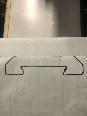
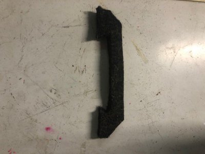
i traced the general size and separated the wiper from the wool.

IMG_4346.jpg IMG_4348.jpg
and tried it out for a test fit in the OEM holder

IMG_4349.jpg

i'll need to duplicate 5 more,
lather rinse repeat as they say!
 
Back
Top