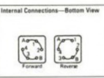
Another Furnas switch question

Nooj

H-M Supporter - Silver Member
Joined
May 25, 2022
Messages
26
I have a single phase, 1/2hp motor that had 6 leads coming from it when I got it. Only 4 we’re connected to the Furnas A-14 switch (and I never saw it run, so I have no idea if they were correct).
The motor data plate does not indicate that there should be 6 wires… the colors aren’t “factory”- the motor has had wires changed and spliced in.
Here’s what I have:
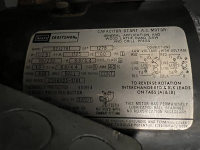
8E4D8D35-6C8F-46E9-9EAA-5972B8AA121A.jpeg

I have black and white wires marked t1 and t2, they read 1.5 ohms across them. (We’ll call them t1 and t2).
I have red and blue wires that read 1.5 ohms between them. (We’ll call them A and B).
And I have black and red wires that read open- but have a capacitance value.

T1 black reads 1.5 ohms to B blue, and .2 ohms to A red.
T2 white reads 1.5 ohms to A red, and .2 ohms to B blue.

The red and black capacitance wires don’t ohm out to any other wires.

What the crap do I have going on here??
It seems like I have two wires for start winding, two wires for run winding (but each set ohms the same and ohms together…), and two wires for start capacitor. But I’m not sure…

Three phase stuff is so much easier.
 
Until you hit a 3 phase motor with dual speed or a "start wye, run delta", either of which will drive you to drink. I'll be back later with some usable details. For now, just be relieved that you only have a single phase to deal with.

.
 
Not sure if these old wiring diagrams from South Bend will be of any help.
9296156d53b053db31512e1b218d79ff.jpg

8fac985ad8f6fef545a1f39254878212.jpg

e5d2bc732cf2e7758e8d60645a6e506c.jpg

4f1b6a5e5323f6a9c3e46dfe196baef7.jpg

2d27c5af2abca24957879fe79f1ef8a7.jpg

317c059a2394b54ca66ed492dafc95a3.jpg

0b496ce1ed1858b7c63bdf20e5657946.jpg


Cutting oil is my blood.
 
3 more
573120e11e732d849d910e7653e2d3a2.jpg

410309ad012e54becbed055084e3be63.jpg

c24edd46a1c18a80ac1d75dedb136057.jpg


Cutting oil is my blood.
 
Need more info to proceed then I can post a sketch for you
Show us both the inside of the drum switch and the motor terminal board (close up views)
-Mark
 
Last edited:
I appreciate all the drawings! My switch is a bit different so that’s throwing me off.

I’ll try to get a decent picture if I can. The motor is installed, so I may have to pull it to get a good view…
 
Ok- here are some pics
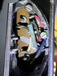
Inside the end of the motor cover:D5FEB42B-E714-4087-858E-771A700D2608.jpeg

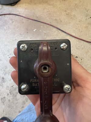
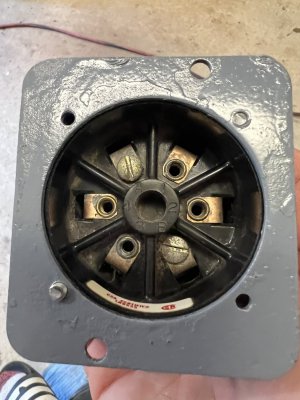
My switch:
8AAC1548-84C8-4669-AE63-ADB8AFB01276.jpeg
186ABF1E-10EA-4D79-A270-962DD249A45D.jpeg


Based on the motor label, I have a red wire on A, blue on B (the two outer most terminals), and black on T1, and white on T4 (the two inner terminals, where it says “line”).
The other black/red pair (the black has the butt splice) go straight into the motor, over to the capacitor I believe.
 
Last edited:
So- tell me if I have this straight:
A & B (red/blue from motor) to 2 &4 on the switch.
T1 & T4 (black/white from motor) to A & B on the switch.
Hot & neutral from the power cord on 1 & 3?

I need the capacitor in series with the start winding though, right?

So… instead, should it be:

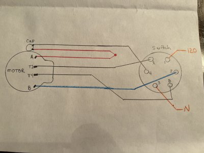
C4D9D246-B96C-414C-B9D7-67E0F336B0F0.jpeg

In this Drawing I’ve just put the cap in series with the start winding.
Perhaps I should’ve put the incoming power on A & B, and t1 & t4 on 1 & 3? Either way, it’s the same electrically, based on the switch makeup

4E346256-3B79-4E1D-A5E9-5A4990BE2D22.jpeg
 
Last edited:
Ok, so… I wired it exactly as my drawing. And tripped the breaker as soon as I turned it on…

:oops2:
 
No surprise LOL give me a bit to study it and I'll put something together
Do you have a continuity checker or multimeter handy? We might need it
Since you haven't seen it run, I think the first thing to do would be to verify the motor starts and runs by itself without the
reversing switch
I can't see clearly but are the links connected as per the low volt case?
We need to figure out why the splice on the black wire and what's up with the blue wire
Ultimately you may need to open up the motor to figure out what is what- probably a good time to dis-mount the motor
and put it up on the bench to work on it
 
Last edited:
Back
Top