Ammco shaper restoration problems

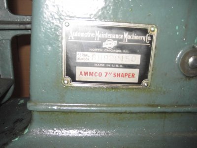
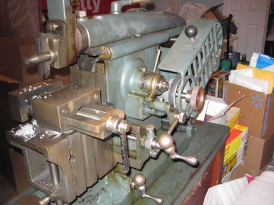
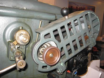
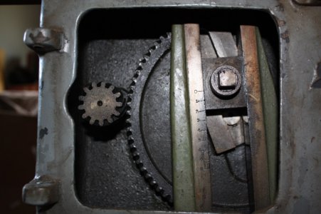
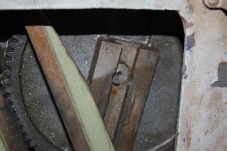
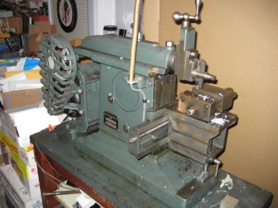
Denton, here are some pictures of my Ammco 7" shaper and info -
IMG_2220.jpgIMG_2221.jpgIMG_2222.jpgIMG_2223.jpgIMG_2224.jpg

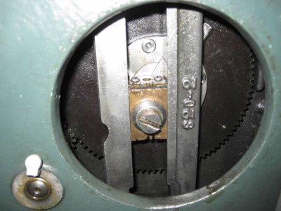
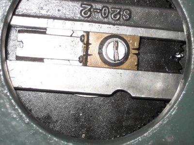
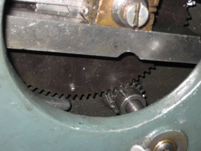
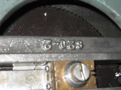
Looking at the last picture, the bronze slide I believe is part number S20-19 the Rocker Arm Shoe, mine is 1-1/2" long and has what looks like a wiper on top. That part is connected to the "slide" (I can't figure out what the part number is or the real name). Mine is 3-3/4" long. The frontside is 3/4" wide x the backside 1" wide (not very accurate measurements as it is hard to access the part), it is 1/4" thick. I will get you more measurements, make a sketch and take better pictures. But this is a start. And......looking at my gears, it looks like I have two spots where there were broken teeth and a repair was made. Paul G

IMG_2220.jpg IMG_2221.jpg IMG_2222.jpg IMG_2223.jpg IMG_2224.jpg
 
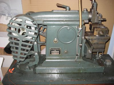
Denton, here are some pictures of my Ammco 7" shaper and info -
View attachment 93493View attachment 93494View attachment 93495View attachment 93496View attachment 93497

Looking at the last picture, the bronze slide I believe is part number S20-19 the Rocker Arm Shoe, mine is 1-1/2" long and has what looks like a wiper on top. That part is connected to the "slide" (I can't figure out what the part number is or the real name). Mine is 3-3/4" long. The frontside is 3/4" wide x the backside 1" wide (not very accurate measurements as it is hard to access the part), it is 1/4" thick. I will get you more measurements, make a sketch and take better pictures. But this is a start. And......looking at my gears, it looks like I have two spots where there were broken teeth and a repair was made. Paul G
I thought I would get started on the crank,( the part you were unsure of the name for ) so used the old one as a guide measured it up and its obviously been remade or repaired. I figured I would make the new crank plate extra long and when I got your measurements I could cut it to length and locate the pin hole. Don't know how to mount the pin onto the plate yet but the old one was brazed. The long and short of it is cut the stock and set the mill to make 60 degree bevels on the edges of the crank plate and merrily milled the plate to width. Then sat down at the computer and was pleasantly surprized to find your pics and measurements. Even though I made the piece 3/4" longer than the original I'm 1/4" too short. OH well the vice is still set up to 60 degrees on the mill so back at it later today. Your help is appreciated Paul.
Denton
 
Denton, a few more pics and info. I measured the "crank", it is 60 degrees and the center of the pin is located 1" from one end.
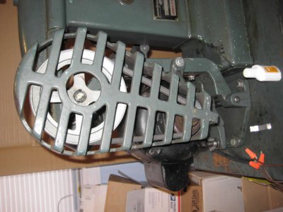
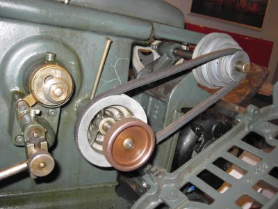
Regarding the motor/drive, more pics are here. Mine has a 1/3 hp 1725 rpm motor with at 2" pulley on it. (note the pulley sizes provided here are the outside dimension of the pulleys as I measured them) That drives the counter shaft 6" pulley. The other end of the counter shaft has a four step pulley: 2", 2-1/2", 3-1/4" and 4". This drives the final pulley which also has a four step pulley: 2", 2-1/2", 3-1/4" and 4".
Regarding the gears inside the housing The small gear is 16 tooth 1-1/8" diameter. The large gear is 96 tooth 6" in diameter. The teeth on the gears is not a straight cut gear tooth....they are twisted, I think they call that splined.IMG_2227.jpgIMG_2228.jpgIMG_2229.jpgIMG_2230.jpgIMG_2231.jpgIMG_2232.jpg
Let me know if you need more info and how you are progressing. I haven't had a chance to use mine, except to do a quick try out. I am looking forward to making some projects like a QCTP for my Atlas 618 Lathe. Paul G

IMG_2227.jpg IMG_2228.jpg IMG_2229.jpg IMG_2230.jpg IMG_2231.jpg IMG_2232.jpg
 
Denton, a few more pics and info. I measured the "crank", it is 60 degrees and the center of the pin is located 1" from one end.
Regarding the motor/drive, more pics are here. Mine has a 1/3 hp 1725 rpm motor with at 2" pulley on it. (note the pulley sizes provided here are the outside dimension of the pulleys as I measured them) That drives the counter shaft 6" pulley. The other end of the counter shaft has a four step pulley: 2", 2-1/2", 3-1/4" and 4". This drives the final pulley which also has a four step pulley: 2", 2-1/2", 3-1/4" and 4".
Regarding the gears inside the housing The small gear is 16 tooth 1-1/8" diameter. The large gear is 96 tooth 6" in diameter. The teeth on the gears is not a straight cut gear tooth....they are twisted, I think they call that splined.View attachment 93526View attachment 93527View attachment 93528View attachment 93529View attachment 93530View attachment 93531
Let me know if you need more info and how you are progressing. I haven't had a chance to use mine, except to do a quick try out. I am looking forward to making some projects like a QCTP for my Atlas 618 Lathe. Paul G

Thanks a million, The mill I'm using is an old atlas I restored. I'm still accessorizing the mill. I had an atlas 618, (great machine) as well but sold it to buy a Myford ML7. I've restored 3 Myford lathes and presently have 2 in the shop having sold one. Well back to the mill. I may get back to you as I' move through this project and find more questions. I'll have to post before and after pics
Denton
 
Denton, a few more pics and info. I measured the "crank", it is 60 degrees and the center of the pin is located 1" from one end.
Regarding the motor/drive, more pics are here. Mine has a 1/3 hp 1725 rpm motor with at 2" pulley on it. (note the pulley sizes provided here are the outside dimension of the pulleys as I measured them) That drives the counter shaft 6" pulley. The other end of the counter shaft has a four step pulley: 2", 2-1/2", 3-1/4" and 4". This drives the final pulley which also has a four step pulley: 2", 2-1/2", 3-1/4" and 4".
Regarding the gears inside the housing The small gear is 16 tooth 1-1/8" diameter. The large gear is 96 tooth 6" in diameter. The teeth on the gears is not a straight cut gear tooth....they are twisted, I think they call that splined.View attachment 93526View attachment 93527View attachment 93528View attachment 93529View attachment 93530View attachment 93531
Let me know if you need more info and how you are progressing. I haven't had a chance to use mine, except to do a quick try out. I am looking forward to making some projects like a QCTP for my Atlas 618 Lathe. Paul G


I have made the steel sliding plate and was wondering how the shaft that the bronze bearing "cube" is mounted to the plate. The screw in the centre of the bearing shown in the ,pics does it go through the shaft and thread into the sliding steel plate to hold the shaft in place?
Denton
 
denton
Those gears are called Helical Gears. Because of the way they engage, they run smoother than spur gears.
However, the angled teeth cause thrust to the gears.
The thrust can be put to use as it is in my Rhodes Shaper.

Here's a pic of the gears in my shaper.
IMG_9287 - Copy.JPG
In this view the pinion gear is thrust toward us and the bull is thrust away from us.
This keeps the bull gear pushed onto the shaft to which it has only a light interference fit.
Only one thrust bearing is needed for each shaft as the generated thrust is in only one direction for each shaft.

Here's a pic of the bull gear with the slide removed so the end of the shaft can be seen.
IMG_9306 - post.jpg
The shaft supports the bull gear but only drives the table feed so there is very little driving force on it. Hence, it has only a light press fit and no retainer.
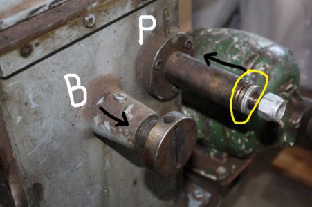
Here's a view of the shafts extending through the case.
IMG_9282 - post.jpg
The black arrows show the direction of thrust for each shaft.
In the yellow oval is the thrust bearing for the Pinion gear.

The thrust bearing for the bull gear sits in a recess just behind the bull ( internal ) and that gear rides against it.
So the thrust induced by using helical gears is needed to keep the bull gear on its shaft and solidly in position in the housing.

I believe that helical gears also run smoother than a chain drive.

You might look at the components of your shaper to see if replacing the chain sprockets with new helical gears would be an improvement.
Don't have a clue where those could be found except perhaps Ebay.
Also, the sliding block and stoke adjustment on my machine are all cast iron. Check what material yours are made of.
Cast iron wears better than steel with less friction and far less chance of galling.
In sliding components there must be room for oil between the components.
Would have to check but I think my slides originally had about 1.5 mills clearance. Similar to what a small bronze bearing would need.

Hope this explanation is of some use or at least interesting to you.
Jim

IMG_9287 - Copy.JPG IMG_9306 - post.jpg IMG_9282 - post.jpg
 
denton
Those gears are called Helical Gears. Because of the way they engage, they run smoother than spur gears.
However, the angled teeth cause thrust to the gears.
The thrust can be put to use as it is in my Rhodes Shaper.

Here's a pic of the gears in my shaper.
View attachment 93790
In this view the pinion gear is thrust toward us and the bull is thrust away from us.
This keeps the bull gear pushed onto the shaft to which it has only a light interference fit.
Only one thrust bearing is needed for each shaft as the generated thrust is in only one direction for each shaft.

Here's a pic of the bull gear with the slide removed so the end of the shaft can be seen.
View attachment 93791
The shaft supports the bull gear but only drives the table feed so there is very little driving force on it. Hence, it has only a light press fit and no retainer.
Here's a view of the shafts extending through the case.
View attachment 93792
The black arrows show the direction of thrust for each shaft.
In the yellow oval is the thrust bearing for the Pinion gear.

The thrust bearing for the bull gear sits in a recess just behind the bull ( internal ) and that gear rides against it.
So the thrust induced by using helical gears is needed to keep the bull gear on its shaft and solidly in position in the housing.

I believe that helical gears also run smoother than a chain drive.

You might look at the components of your shaper to see if replacing the chain sprockets with new helical gears would be an improvement.
Don't have a clue where those could be found except perhaps Ebay.
Also, the sliding block and stoke adjustment on my machine are all cast iron. Check what material yours are made of.
Cast iron wears better than steel with less friction and far less chance of galling.
In sliding components there must be room for oil between the components.
Would have to check but I think my slides originally had about 1.5 mills clearance. Similar to what a small bronze bearing would need.

Hope this explanation is of some use or at least interesting to you.
Jim

Thanks Jim, I'm into the chain drive for now. Someone said Boston gear had metal substitutes for the gears but I'll leave that for later failing the chain drive. I have all the shafts fitted and am working on fixing the shoe adjustment lock. A buddy with a tig is going to weld it for me tomorrow. This and a #35 chain and sprockets should get me to assembly then make up a counter shaft assembly for the motor the original was gone and what it had was a very poor replacement.
 
I am going to have to replace some missing components with whatever I can cobble up as well.
Mine is missing the counter shaft and both sets of flat belt sheaves.
Will probably set it up with V-belt sheaves.
Rite now I'm working on a 60 deg. straight edge so I can get my mill/drill and lathe scraped into better shape so I can make the 50 deg. straight edge needed for the shaper rebuild
and do a better job fabricating parts.
The fun never ends !
 
I'm researching the Ammco gears and can find pics but no technical information or source for new gears. I need diameters, tooth counts, the ratio ( turns small gear to turn the large one revolution) and the angle the teeth are cut. If I understand correctly they are a helical cut gear. If someone know any additional information I would appreciate it.
Denton
 
So far I have done two different runs of phenolic bull gears for the Aamco shapers, identical to the originals, I sold them all on ebay, 35 all together I think. The big killer of the phenolic gears is swarf and chips entering the column, they won't hold up to that kind of abuse, and steel gears don't like chewing up chips either. I suspect people who use air for cleaning machine tools have destroyed more machine tools than every other cause put together. I make the blanks with the pressed in straight knuled nuts, and send them to a gear house to have them hobb the teeth. Never had a complaint except when I run out.
partsproduction
 
Back
Top