-
Welcome back Guest! Did you know you can mentor other members here at H-M? If not, please check out our Relaunch of Hobby Machinist Mentoring Program!
You are using an out of date browser. It may not display this or other websites correctly.
You should upgrade or use an alternative browser.
You should upgrade or use an alternative browser.
4th Axis Trunnion Table project
- Thread starter spumco
- Start date
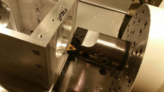
Dear god, how long did it take to line bore that housing. That looks miserable.
Not that bad, honestly. I used a high-polish positive rake insert (not in the photo), and I milled the bearing pocket out to within about 0.075" of final bore in a vise (with the normal spindle). The line boring was just a way to ensure Z-axis concentricity. Took about 4 passes per pocket until I got a thumb-force press fit. And the pockets are only 0.750" deep(ish).
Did the front end, then unbolted the ball nut, slid it off the rails, and flipped it end for end. The rails kept everything aligned for the outboard pocket.
Glue the bearings in with some retaining compound and done deal.
But yes, it took some time at 30RPM. First pass I wound up advancing the tailstock too quickly and got really nice threads instead of a smooth bore.
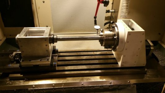
A better photo below of the setup right before I switched inserts. Second one is final alignment before tightening the tail base plate down. Got a 1" hardened chrome rod trued up in the 4-jaw and then clamped the other end in a 1" collet with the tailstock loose. Tapped it in true while rotating the rod to average the errors and then snugged up the 4th axis and tail base.
The rotational axis of the 4th and tail are concentric, parallel with the X, and perpendicular to Z within the limits of my ability to measure - maybe a couple of tenths here or there.
-Ralph


50:1 (or 51:1 to be exact).What reduction ratio did you go with on the harmonic drive?
I'd like to say that this was the precise ratio I needed, based on a careful engineering study. Reality was that I was looking for anything 100:1 or less and got the 50:1 drive dirt cheap. I wanted something fast - I was tired of 10RPM on my worm drive 4th - and lucked in to this one.

