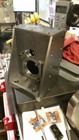
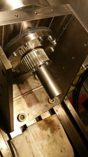
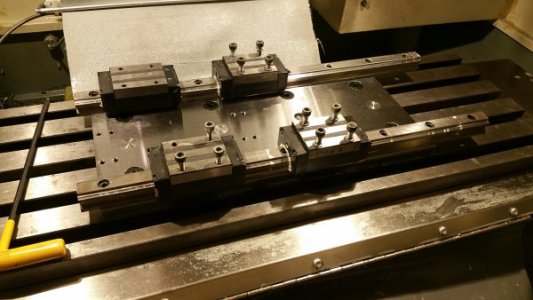
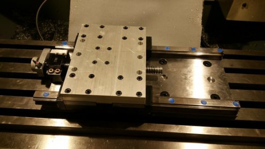
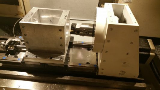
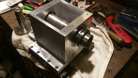
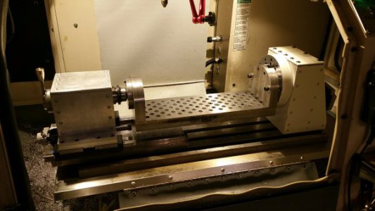
At the request of TomS, here are some details of a trunnion table I recently built to take advantage of my 4th axis.
Basic idea was to have a very heavy-duty trunnion table that was as big as my machine travels permitted, but that was easy to remove so I could stick a 6" vise or other stuff on the table. Also wanted a fairly standard hole pattern for fixtures.
Biggest issue to overcome was the fact that I don't have a hoist in my garage, so I couldn't just make a big base plate to mount the drive and tail support in one piece for easy setups. Way too heavy for me to lift. That meant making the trunnion removable while still being repeatable.
Answer to that was:
1. Make the tail axle removable. Loosen the axle clamp screw, and the axle slides out of the trunnion tail plate. The axle doesn't rotate with the plate (the plate has a bronze bush pressed in) so no fussy bearings as this thing only rotates at about 8RPM max. That, and I has some bronze stock on hand.
2. There is a locating pin in the 4th axis spindle with a 2MT end and a straight-side .875" end. The 2MT end goes in the spindle and the other end sticks out about .625". The drive plate has a slot/pocket in the end with two angled shoulders at the bottom. Those shoulders are tangent to the center of rotation, and bear against the locating pin.
3. Installation of the trunnion means turning it upside down, dropping the pocket/slot over the drive end locating pin until the shoulders hit the pin, and sliding the tail axle in the bush. Run the drive screws in to the faceplate T-nuts and snug everything down. Because the pin only touches the drive plate pocket at the intended contact surfaces, there's no 'nudging' anything around to get it back to square and parallel along the X-axis. Nor do I have to worry about pushing a pin with clearance through the drive end in to the 4th spindle and then having it bind up if I'm off a bit. There's zero clearance between the pin the the drive pocket contact surfaces. All I have to do now is bolt it in and sweep the table along Y to zero the A-axis.
Materials - I went with hot rolled steel. I considered aluminum, but steel is about 3x stiffer than aluminum and I didn't want any flex. And hot rolled doesn't warp as much as cold-rolled or some of the alloys. It's not heat-treated or hardened - what was the point? If I ding the table I'll just stone it out.
Everything is a simple milled surface, except for the working table surface. I used a buddy's surface grinder to flatten that down and it looks like pretty awesome. A tenth's indicator on the middle of the table barley twitches when I stand on the table - no flex.
Size - The table is 1.25" (ish) finished thickness, and 5.5"x18" long. Working surface is about 16" long. Height/offset from rotational axis was as far as I could get it with main plate thickness. Had to chamfer the edges about 3/4" to get them to clear the table. Working surface is 2.008" from the rotational centerline
Features:
1. Holes are tapped 3/8-16, and the top .5" is reamed for 3/8 dowl pins. Totally stole that idea from Saunders Machine Works (NYC CNC - youtube) and it's an excellent idea. Pattern is 1"x1" triangle pattern, so holes along the X & Y axis are 2" apart. Center of hole pattern is aligned with the rotational axis.
2. The fixed axle and floating tail end plate mean that when the table grows in length due to temp changes it doesn't bind up. There's about .025-.050" clearance between the tail support and the outboard end of the tail plate.
3. All connections are bolted, and there's enough slop that everything is adjustable. I knew I couldn't machine it that perfect, so during initial indication & squaring I just snugged it all up lightly and got the tail axis dead-nuts with the 4th drive axis (brass shims under tail support). After that, I rotated the 4th a whole bunch of times to let it settle in without binding and then started slowly tightening all the connection joints. Dowel holes were nudged parallel with the X-axis and the table was finally tightened to the drive/tail plates.
Future Changes:
1. If I did it again, I'd avoid screwing up the intended hole pattern. Completely my fault, but I exported a bad version of the CAD file that had the inboard hole pattern off-set by about .1" and then went and machined it out on my buddy's VMC. Now the 2nd and 4th row of holes is offset along X and none of my fixtures are reversible! Still perfectly usable - I just have the 'final' version saved in CAD so when I model a fixture I set the fixture hole/dowel pattern to the as-built pattern.
2. Make it longer. If it were about 2-3" longer I could get the mill head all the way down to the working surface at the extreme ends of the machine travels. I'd still have room on the machine table for the 4th drive and tail support. Not a huge deal, but now it's a bit limited in working length if the parts are really off-set from the rotational axis.
So, there you go. Just ignore the naughty little part in the fixture...
-Spumco
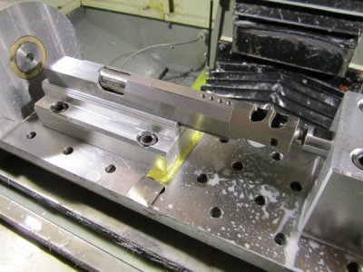
Overview. Note brass shims under tail support go get the axis lined up with the 4th drive. Also note the total hack-job splash shields over the 4th stepper and top.
The big block to the right is a tail-stock with a retractable ram that supports the long overhanging part (currently retracted).
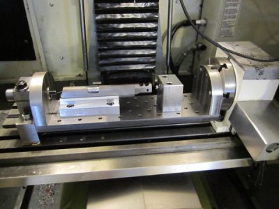
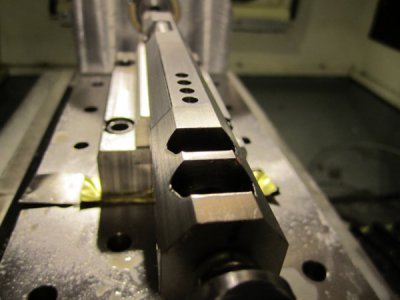
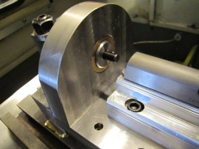
Closeup of tail end. Dowel pin in center of axle is used to find Y/Z zero. Fusion 360 CAM requires all 4th axis moves to use the center of rotation as the WCS and tool orientation references, so this was way easier than swinging the table around and indicating the table surface a bunch of times.
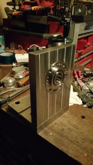
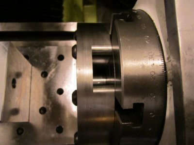
Here's a shot looking down the drive plate slot/pocket. You can just see the locating pin at the bottom. When it's upside down, the angle surfaces at the end of the pocket bear against the pin. There's clearance between the end of the pin and the bottom (left in photo) of the pocket.
Basic idea was to have a very heavy-duty trunnion table that was as big as my machine travels permitted, but that was easy to remove so I could stick a 6" vise or other stuff on the table. Also wanted a fairly standard hole pattern for fixtures.
Biggest issue to overcome was the fact that I don't have a hoist in my garage, so I couldn't just make a big base plate to mount the drive and tail support in one piece for easy setups. Way too heavy for me to lift. That meant making the trunnion removable while still being repeatable.
Answer to that was:
1. Make the tail axle removable. Loosen the axle clamp screw, and the axle slides out of the trunnion tail plate. The axle doesn't rotate with the plate (the plate has a bronze bush pressed in) so no fussy bearings as this thing only rotates at about 8RPM max. That, and I has some bronze stock on hand.
2. There is a locating pin in the 4th axis spindle with a 2MT end and a straight-side .875" end. The 2MT end goes in the spindle and the other end sticks out about .625". The drive plate has a slot/pocket in the end with two angled shoulders at the bottom. Those shoulders are tangent to the center of rotation, and bear against the locating pin.
3. Installation of the trunnion means turning it upside down, dropping the pocket/slot over the drive end locating pin until the shoulders hit the pin, and sliding the tail axle in the bush. Run the drive screws in to the faceplate T-nuts and snug everything down. Because the pin only touches the drive plate pocket at the intended contact surfaces, there's no 'nudging' anything around to get it back to square and parallel along the X-axis. Nor do I have to worry about pushing a pin with clearance through the drive end in to the 4th spindle and then having it bind up if I'm off a bit. There's zero clearance between the pin the the drive pocket contact surfaces. All I have to do now is bolt it in and sweep the table along Y to zero the A-axis.
Materials - I went with hot rolled steel. I considered aluminum, but steel is about 3x stiffer than aluminum and I didn't want any flex. And hot rolled doesn't warp as much as cold-rolled or some of the alloys. It's not heat-treated or hardened - what was the point? If I ding the table I'll just stone it out.
Everything is a simple milled surface, except for the working table surface. I used a buddy's surface grinder to flatten that down and it looks like pretty awesome. A tenth's indicator on the middle of the table barley twitches when I stand on the table - no flex.
Size - The table is 1.25" (ish) finished thickness, and 5.5"x18" long. Working surface is about 16" long. Height/offset from rotational axis was as far as I could get it with main plate thickness. Had to chamfer the edges about 3/4" to get them to clear the table. Working surface is 2.008" from the rotational centerline
Features:
1. Holes are tapped 3/8-16, and the top .5" is reamed for 3/8 dowl pins. Totally stole that idea from Saunders Machine Works (NYC CNC - youtube) and it's an excellent idea. Pattern is 1"x1" triangle pattern, so holes along the X & Y axis are 2" apart. Center of hole pattern is aligned with the rotational axis.
2. The fixed axle and floating tail end plate mean that when the table grows in length due to temp changes it doesn't bind up. There's about .025-.050" clearance between the tail support and the outboard end of the tail plate.
3. All connections are bolted, and there's enough slop that everything is adjustable. I knew I couldn't machine it that perfect, so during initial indication & squaring I just snugged it all up lightly and got the tail axis dead-nuts with the 4th drive axis (brass shims under tail support). After that, I rotated the 4th a whole bunch of times to let it settle in without binding and then started slowly tightening all the connection joints. Dowel holes were nudged parallel with the X-axis and the table was finally tightened to the drive/tail plates.
Future Changes:
1. If I did it again, I'd avoid screwing up the intended hole pattern. Completely my fault, but I exported a bad version of the CAD file that had the inboard hole pattern off-set by about .1" and then went and machined it out on my buddy's VMC. Now the 2nd and 4th row of holes is offset along X and none of my fixtures are reversible! Still perfectly usable - I just have the 'final' version saved in CAD so when I model a fixture I set the fixture hole/dowel pattern to the as-built pattern.
2. Make it longer. If it were about 2-3" longer I could get the mill head all the way down to the working surface at the extreme ends of the machine travels. I'd still have room on the machine table for the 4th drive and tail support. Not a huge deal, but now it's a bit limited in working length if the parts are really off-set from the rotational axis.
So, there you go. Just ignore the naughty little part in the fixture...
-Spumco
Overview. Note brass shims under tail support go get the axis lined up with the 4th drive. Also note the total hack-job splash shields over the 4th stepper and top.
The big block to the right is a tail-stock with a retractable ram that supports the long overhanging part (currently retracted).

Closeup of tail end. Dowel pin in center of axle is used to find Y/Z zero. Fusion 360 CAM requires all 4th axis moves to use the center of rotation as the WCS and tool orientation references, so this was way easier than swinging the table around and indicating the table surface a bunch of times.

Here's a shot looking down the drive plate slot/pocket. You can just see the locating pin at the bottom. When it's upside down, the angle surfaces at the end of the pocket bear against the pin. There's clearance between the end of the pin and the bottom (left in photo) of the pocket.


