Hi
Dustooff,
Here are my specs:
Spindle: 1-1/4" D (before machining) x 6.25" L, Steel, Rockwell C60-C65
Bearings: SKF 32306, 1.1811" ID, 2.8346" OD, 1.1319" Thickness
Bearing Seals: Timken 473448, 1.750" ID, 3.001" OD, .375" Thickness
Large Pulley: 60-Tooth
Small Pulley: 10-Tooth
Gear Ratio: 10:1
Housing 6061-T6 Aluminum (might not have been a good choice), 4" x 5" x 6"
Chuck: 3", 4-Jaw, independent
Motor: KL23H276-30-8B, 1.8°, 200-Step, NEMA23 282oz-in 3A Stepper Motor ¼-Inch Dual shaft
Driver: M542 CNC Stepper Driver Controller 2/4 Phase, 256 Microstep, Multiple Subdivision
Theoretical Maximum Resolution: 50,000 Steps Per Revolution (1.8° Motor) = 0° 0' 25.92", or ≈ 26 Arc-Seconds
This is my first attempt at doing anything like this, so maybe it's impressive, maybe not.
As for the drawing, I've been designing everything in Excel - electronics, mechanics, woodworking, etc. - since the 90's. I find it to be a
very useable drawing tool, but you have to create all the parts from scratch, and to perfect scale, for it to work. Additional benefits include parts lists, calculations, commentary, notes, etc. Also, the compatibility can't be matched - everyone has Excel. Therefore, I can send my work to almost anyone in the world and have no problems with compatibility.
DMS:
Very cool video!
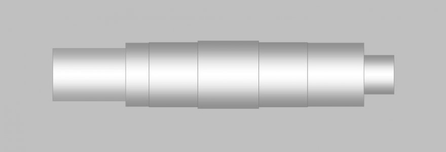
Here is a drawing of the spindle before threading:

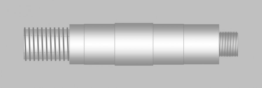
After threading with Taper (2MT):

Jim


