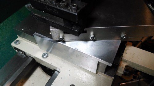
29.5 Deg. Angle Tool For Lathe

RJ, Could you show me a picture of where/how you use this on your 602? I have the VFD version the that lathe and would like an easy way to set it for threading. I know exactly what you mean about hard to see/read the dial on the compound.

Jim
Jim, The vertical side mates to the left hand vertical surface of the cross slide. The vertical edge of the triangle mates to the left hand vertical edge of the compound base. I have a beefed up compound clamp, the corner of which is visible as a vertical surface above the cross slide and below the 90 degree angle on the triangle. It is slightly inset from the slide so I am referencing the slide and not the clamp.

Bob
Gage in Use  .JPG
 
Bob,

That helps! I also like your "hole covers" in the follow rest holes. I should do that, I just have the bolts from the rest in there and they get in the way when trying to brush chips away.

Thanks

Jim
 
Bob,

That helps! I also like your "hole covers" in the follow rest holes. I should do that, I just have the bolts from the rest in there and they get in the way when trying to brush chips away.

Thanks

Jim
The bolts were leftovers from one of the Grizzly installs I did. I would have preferred a flatter head on them but that was an easy fix.
 
I've revised my "need" for accuracy. Anything less than 30° is good.
 
I've revised my "need" for accuracy

Agreed, used to do the same thing with the mill DRO that reads four places, the time spent chasing that last digit was almost always a waste of time, so is chasing that 29.5º using a Chinese protractor :) I do like RJ's method though, no chasing just set it. On my lathe, once set, I scribed mating lines on the compound base and rotating part with the degrees on it, makes it pretty quick to set when needed also. The mating lines can be put anywhere easy to see since it is just a reference.
 
I guess I do chase the tenths around on my DRO. I know that I am not machining to the accuracy indicated but I do so for two reasons. One is that the total accuracy is made up of a number of different components, the DRO reading is one.

It is kind of like sighting a rifle. My hand isn't that steady so do I have to be sighted in to an eighth of an inch? If I am off two inches to the right, my groups should cluster about that offset which increases the probability that I will miss my intended target. It costs me little in time to make that final adjustment so I do it.

The second reason is when I am running manually, I read the dimensions from my drawing and set the DRO to match. I usually use ordinate dimensioning and set my DRO origin to match. In my advancing years, my poor brain does not always function as well as it should so having a DRO reading exactly match the the drawing value is a mental check for me that I am doing what I intended to do. I use four decimal place on the drawings for the same reason. Note that these are for my personal use and not intended to communicate any implied accuracy to others. For me, the cost is minimal and the benefit is significant.

Disclaimer: I am not running a for profit machining business and I am retired so I am not concerned with a little extra time spent. I probably also suffer from OCD as well.:laughing:
 
I'll end up in the area of four places but no more chasing the precise digit, I still have to fight not chasing though :D
 
" I am retired so I am not concerned with a little extra time spent. I probably also suffer from OCD as well."

I probably should have written the above, myself.
 
Randy, I believe I said that in the last post. However, with my G0602 anyway, the dial has 2-1/2 degree graduations and is buried where it is difficult for me to read. On top of that, it has an offset as well. Being able to loosen the bolts, slide the gage in and retighten is worth the hour or so spent machining the gage.
Interesting that the title on the lower left illustration says "15 to 29-1/2 Degrees Infeed Angle" while the illustration says 1 -3 degrees.

Bob, I noted that angular difference too but just assumed that he was illustrating that his cutting tool was set within 1 to 3 degrees of 30 degrees in that specific example, not that he was suggesting that it was the total allowable angular variation. Perhaps if he'd drawn the angles to depict the full movement from 15 to 29.5 degrees, the sketch would have been cluttered and confusing ?

Yes you did note that the 29.5 degree angle wasn't cut into stone tablets - I've posted your statement below in case anyone missed it in the first reading. My point was not to contradict anything that you (or anyone) said specifically but to illustrate how some sacred cows don't have to be taken seriously and just how widely the compound angle can change while producing perfectly acceptable threads.

...There isn't anything really sacred about the 29.5 degree angle. Its intent is to shave a small amount of the left hand side of the thread as you advance the cut. The South Bend book "How to Run a Lathe" recommends a 29 degree angle.
 
Nice work on your project. But this subject gets pounded to death on angle this and angle that. And I’m still gonna say, ”I go straight in with the cross slide only”. And I’ve been doing it that way for about 40 years now. Look at all that time I have save not messing around with the compound angle adjusting. And my threads look great. And my lead does not change so I can do trick things to the end of the thread too. And threading up to a shoulder is easier because your tool does not creep to the left. Try it, you might like it…Good Luck, Dave.
 
Back
Top