210mm swing Electronic Leadscrew lathe now available

Hi Southern Chap,

What pics do you think would be most illustrative for our members?

Malcolm
I guess the usual beauty shots of the lathe in its habitat (AKA your shop), shots of the quirks, peculiarities, and flaws you mention (wherever convenient; not asking you to disassemble the thing! :grin:), and finally, some pictures of the ELS display/control interface.

You don't have to post pictures, of course, but it'd brighten up the place if you would. :)
 
Will be out of town for a couple of weeks. Will post a photo essay on my return.
Malcolm
 
I'm not an affiliate so I won't place direct links, but you should find it by googling "lathe 1100w electronic".
The manufacturer representative. pointed me to it while discussing other matters, the first thing I suggested is that they remove the the change gears table on the quadrant cover :oops: - I didn't manage to get a a sound "yes we will".
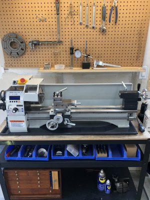
What I like is the brushless 1.1kW motor and that the belts to the spindle are properly sized, unlike the terrible VEVOR one that are 3mm for the same motor!
Bed length is probably excessive at 800mm, it increases weight and cost for no major advantage for the majority of hobby users.
I suspect that the leadscrew is metric, but that is a non-issue with E-LS.
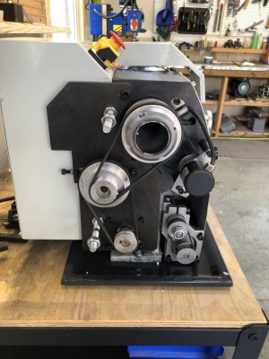
It seems to me that these have 100mm bed width, with the casting feet very narrow, the machine needs to be bolted down or it will be unusable.
The building details appears decent, with the tailstock and apron left unpainted, but blackened. Personally I like that as it makes so much easier to repair the occasional damage. Of course some things they will never get right, as in using black jam nuts for the traverse and compound jibs, or Heaven forbids, locking screws there.
The E-LS appears easy to control, but from on the attached video doesn't possible to set non-standard pitches, sometime necessary to cut non-metric, non-imperial thread, yes they do exist try making screw for antique French clocks. Or for coiling springs, etc.
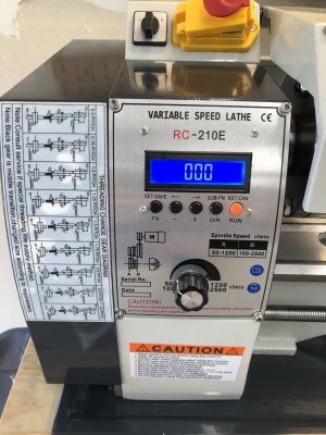
Here's a flow chart showing how the program is organised. See the section on threading to see how to input non-standard thread pitches.
 

Attachments

  • lathe flowchart.pdf
    89 KB · Views: 9
Here's the first installment of the promised photo essay.

The first few show the packing. Nice crate. A nightmare if you don't like Styrofoam and a lot of dirty oil covering the lathe once you get the plastic wrap off.

One shot of the meager accessories in the toolbox (chuck and dead center are shipped installed on lathe).

The picture of the bed shows an arrow pointing to one of the mounting holes in the bed foot. The other is at the headstock end and is inaccessible with the lathe still in the box. They are M8, the heads are recessed deep inside the crate 'blocking' and either end is free to spin - making getting at both ends at the same time mandatory. Difficult on the tailstock end. Impossible to do on the headstock end. I ended up cutting the bolt head off on the headstock end and then driving it thru. I was then able to lift it out using my tractor bucket.

The chip pan has too holes. They are not centered on the pan axis, but are offset somewhat. I probably doesn't matter, but I opted to place the lathe further back on the pan. I used the pan as a template, drilled through the bench top, and then double sided taped the pan to the bench so it would move when locating the lathe.....See comments re: getting it out of the crate...

Last few pics show the lathe installed on the bench, the business end of the lathe and a shot of the control panel and hilariously unnecessary change gear table....

I'll follow up later with a few more closeups and descriptions. If anyone would like to see anything in particular, let me know.

Cheers - Malcolm
 

Attachments

  • Img_2741.jpg
    Img_2741.jpg
    276 KB · Views: 17
  • Img_2740.jpg
    Img_2740.jpg
    258 KB · Views: 21
  • Img_2739.jpg
    Img_2739.jpg
    306.9 KB · Views: 19
  • Img_2738.jpg
    Img_2738.jpg
    238.9 KB · Views: 16
  • Img_2737.jpg
    Img_2737.jpg
    241 KB · Views: 13
  • Img_2736.jpg
    Img_2736.jpg
    271.9 KB · Views: 17
  • Img_2735.jpg
    Img_2735.jpg
    264.8 KB · Views: 15
  • Img_2733.jpg
    Img_2733.jpg
    279.8 KB · Views: 15
  • Img_2732.jpg
    Img_2732.jpg
    224.4 KB · Views: 15
  • Img_2731.jpg
    Img_2731.jpg
    330.4 KB · Views: 14
  • Img_2730.jpg
    Img_2730.jpg
    356.5 KB · Views: 18
Here's the first installment of the promised photo essay.

The first few show the packing. Nice crate. A nightmare if you don't like Styrofoam and a lot of dirty oil covering the lathe once you get the plastic wrap off.

One shot of the meager accessories in the toolbox (chuck and dead center are shipped installed on lathe).

The picture of the bed shows an arrow pointing to one of the mounting holes in the bed foot. The other is at the headstock end and is inaccessible with the lathe still in the box. They are M8, the heads are recessed deep inside the crate 'blocking' and either end is free to spin - making getting at both ends at the same time mandatory. Difficult on the tailstock end. Impossible to do on the headstock end. I ended up cutting the bolt head off on the headstock end and then driving it thru. I was then able to lift it out using my tractor bucket.

The chip pan has too holes. They are not centered on the pan axis, but are offset somewhat. I probably doesn't matter, but I opted to place the lathe further back on the pan. I used the pan as a template, drilled through the bench top, and then double sided taped the pan to the bench so it would move when locating the lathe.....See comments re: getting it out of the crate...

Last few pics show the lathe installed on the bench, the business end of the lathe and a shot of the control panel and hilariously unnecessary change gear table....

I'll follow up later with a few more closeups and descriptions. If anyone would like to see anything in particular, let me know.

Cheers - Malcolm
Kind of comical with the gear chart on the swing out door! They should have saved that sticker for a different lathe.
 
Here's the first installment of the promised photo essay.

The first few show the packing. Nice crate. A nightmare if you don't like Styrofoam and a lot of dirty oil covering the lathe once you get the plastic wrap off.

One shot of the meager accessories in the toolbox (chuck and dead center are shipped installed on lathe).

The picture of the bed shows an arrow pointing to one of the mounting holes in the bed foot. The other is at the headstock end and is inaccessible with the lathe still in the box. They are M8, the heads are recessed deep inside the crate 'blocking' and either end is free to spin - making getting at both ends at the same time mandatory. Difficult on the tailstock end. Impossible to do on the headstock end. I ended up cutting the bolt head off on the headstock end and then driving it thru. I was then able to lift it out using my tractor bucket.

The chip pan has too holes. They are not centered on the pan axis, but are offset somewhat. I probably doesn't matter, but I opted to place the lathe further back on the pan. I used the pan as a template, drilled through the bench top, and then double sided taped the pan to the bench so it would move when locating the lathe.....See comments re: getting it out of the crate...

Last few pics show the lathe installed on the bench, the business end of the lathe and a shot of the control panel and hilariously unnecessary change gear table....

I'll follow up later with a few more closeups and descriptions. If anyone would like to see anything in particular, let me know.

Cheers - Malcolm
my MX-600A came in the same crate, i took the screws out at the bottom then lifted the 4 sides with the top still attached to use as a cover later also made getting to the bolts holding it to the base easy.

nice lathe congrats
 
Here's my first stab at a video. Please excuse the shaky camera work and delivery, but hopefully, it will provide some insight into how the RC-210E works.
it is not swing out, you pull it off and set it aside where you can see the charts.
As far as the RC-210E is concerned, the best solution is a heat gun and gentle tugging to get it off...
 
site won't accept a large video, so I'll have to figure out how to compress it and try again later - Malcolm
 
Here's my first stab at a video. Please excuse the shaky camera work and delivery, but hopefully, it will provide some insight into how the RC-210E works.

As far as the RC-210E is concerned, the best solution is a heat gun and gentle tugging to get it off...
 

Attachments

  • VideoCompressorResizeCompressVideo2024_09_18_01_04_35.mp4
    40.1 MB
Back
Top