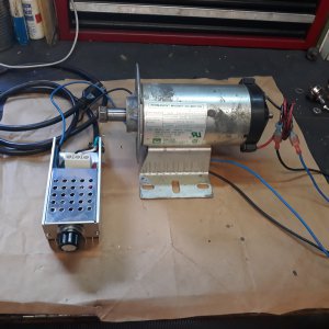
The Inductor-Capacitor low-pass filter limiting the transient is the elegant way to do it, but the downside is, as has been pointed out by
@Alexander McGilton, the components store large amounts of energy in the inductor magnetic field. On switch-off, it tries to come out, generating unwelcome voltages in the process, capable of spot-melting and sticking, ultimately burning out contacts.
Another way is to use low value wire-on-ceramic resistors, and a cheap relay timer, and a motor contactor. The timer is configured to ON-DELAY for a time enough to take out the surge, and allow the motor to spin up some. Once the armature is spinning, it will be generating it's back-EMF, which subtracts from the applied voltage, leaving only enough to keep the off-load motor spinning via the resistor, which limits the current anyway.
Then, the delay timer runs out, and operates the motor contactor to short out the resistor, and apply the full voltage.
It was my version of a cheap soft-start, and it worked well. I used 47-ohm resistors in one, and 15-ohm resistors in another, but the best value for you has to be worked out for your motor.
Remember that if you rectify 110VAC, you get a voltage 1.414 x 110 = 155.5 volts.
Connecting that on a 2kW motor which is at a standstill leaves only the (very low) resistance of the armature copper. That is pretty much a short-circuit until the motor gets going. A few shots of that would not have been kind to the commutator and brushes.
Another thing to consider is using an AC universal brush motor on DC when it was likely designed for AC may have problems. Like any motor with brushes, the field coils voltage stays in step with the armature voltage, so the motor turns the same direction, despite it has AC applied. It will turn OK with DC also, but the difference is that when using AC, the inductance of the motor windings goes some way to limiting the current at 60Hz, on every cycle. When you hit it with DC, in the milliseconds before it spins up, the inductance gets only one shot at limiting the transient, and the current goes up to whatever the (low) DC resistance lets it level out at. This is why I used an external resistor.
The same thing happens with AC on a cheap site isolation transformer with not enough copper and iron in it. It has a switch-on surge that tries to be x10 to x20 the current it normally has when the alternating field is established. Putting power into a magnetic thing which has only got metal in there without any field is like offering a near short-circuit.
I would be wary of using a dimmer-style AC power control on anything except a resistive load. It relies in the AC output to swich off the triac every cycle. If you rectify, and then add inductive load, and perhaps capacitor, you can seriously modify the waveform it relies on. That arrangement may also generate the father and mother of RF interference on your mains waveform. There is a reason that proper semiconductor power controllers have input filtering, and power factor correction, and much higher frequency switching. The components like inductors and capacitors can be so much smaller.
I am all for re-purposed kit. I do it myself, but normally, I keep the stuff using the kind of power it was designed for.
@RJSakowski has very good advice about semiconductor power controllers. The kind you would use for a dimmer has a simplistic phase control to alter when the triac switches. One can use solid state relays, for AC or DC, and I love them. There is a common kind which only switches on the AC as the voltage passes through zero, and another kind that switches the instant the gate is opened. I have discovered that if one controls the switch-on (AC) to happen when the voltage is still high, but on it's way down, at about 80% of the peak. then the current trying to surge is faced with a voltage that is heading for zero, and is going to get there in about 3 milliseconds. You can almost eliminate the switch-on surge.


