10F with TH54 bed....getting it running again.

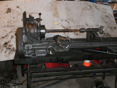
Here's a picture of the whole lathe for ya. Tried to do a little turning on a tranny shaft but it was a bit too hard for my dull bits and lack of technique. Today I try to sharpen some of the HSS bits I have, did a LOT of reading on it last night. One thing I read was a little surprising to me and something I used to do but thought I was being a cob job mechanic. Someone said don't bother using the tool holders unless you HAVE TO..just put the bit itself in the toolpost. I have done that, stacking 3/8 bits to get it to a good height, and had OK results...Should I keep doing it that way or make new and sharp bits for my 1/4 inch holders?


I already figured out not to let the compound get too extended...If I keep it back over its base it doesn't seem any where near as flexible. I also think I need to work on adjusting the gibs for the saddle and another of todays jobs is leveling the lathe and getting it firmly bolted down to its stand in ALL the bolt holes. :madebooboo:


Interesting smiley assortment we have here!! Anyhow, the PIC:
DSCN1657_zps872783a2.jpg
 
Using a short piece of non hardened steel stock with just a couple of inches sticking out of the chuck will give you much more rigidity than what you are doing in the pic.

If you have some stock 2"-3" or so diameter this will allow you to experiment with different spindle speed/feed rates every few passes as you turn it down. I found this useful when I was getting used to my Atlas.

Mounting the tool direct into the lantern is fine, just remember the tool angles are different when the tool is flat, rather than tipped up in a tool holder.

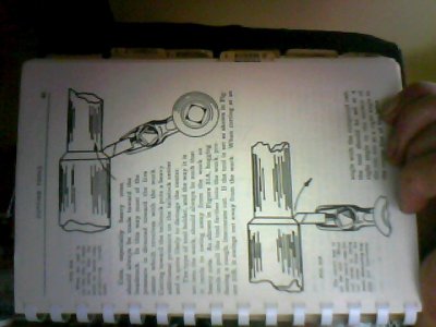
Hard to explain, but it can be helpful to angle the tool bit ever so slightly towards the tail stock, (the pic by nearest hand) this way the tool is forced away from the cut is if starts digging in if you get something wrong, as it is forced away from the center.

image_sb_7.jpg


look here for some basic info on speeds http://en.wikipedia.org/wiki/Speeds_and_feeds

Enjoy

Bernard

image_sb_7.jpg
 
Last edited:
Yup, last night I spent a few hours in the shop experimenting with a thick walled piece of pipe trying to get it centered in my three jaw , facing it and turning it down a little. It was pretty awesome to use the leadscrew to move the carriage back and forth but I think I need to gear it down a bunch. With only three or four gears (59 and 64 and 20 tooth ones that came with it) I haven't figured out how to do that yet. If I want a nice smooth finish besides the tool sharpening issue I mentioned, I have to hand feed...which is how I used to do it. Also hitting the piece with a file will work but that's cheating.

Will my four jaw grab the short piece better than my three jaw? It feels like it doesn't grab tight enough but I don't want to tighten the single adjusting screw any more....it doesn't seem to take much to knock it 10-20 thou off center at the end that is sticking out maybe 5 inches.

I read ya about making sure the bit won't dig in if it catches....and also I know about getting it on the centerline, not above or below. Easier said than done on the latter but what a difference when I get it close to right!

I've got a lot of learning to do before I make my die set for the bead roller it seems. I wandered around the local scrap yard for an hour yesterday and didn't find any 3 inch stock to make it from anyhow. (I did get some nice square stock that will work perfect for my hydraulic press though, and a nice chunk of diamond plate for a workbench. Also picked up some smaller thick walled pipe and solid rod to play with.)
 
just a quick pointer..
if you don't know if you are off center with your toolbit...
put a dead center in the tailstock, bring your tailstock close to the toolbit, loosen your toolpost screw, lift or lower the tool to match the point of the dead center, lock the toolpost screw, then recheck ....BADDABING you're on center!
i hope it helps!
 
Bill,

The slowest easily obtainable feed (assuming that you have a 3/4" dia. lead screw) is .0035, which needs 2X20T, 2X64T, 48t & 52t.

The 4-jaw would be a little more rigid than the 3-jaw because of increased surface area in contact and decreased angle between the jaws. However, I would check the jaws in the 3-jaw for bell-mouthing (the right end of the jaw is at a slightly greater diameter than the left end when clamped. To do this, you have to be able to load the jaws and still leave the contact surfaces open so that you can run an indicator down them. Two ways to do this - three pins inserted into the fronts of the jaws or 4-hole ring. This is also the setup for re-grinding the jaws.

Thanks for the photo.

Yup, last night I spent a few hours in the shop experimenting with a thick walled piece of pipe trying to get it centered in my three jaw , facing it and turning it down a little. It was pretty awesome to use the leadscrew to move the carriage back and forth but I think I need to gear it down a bunch. With only three or four gears (59 and 64 and 20 tooth ones that came with it) I haven't figured out how to do that yet. If I want a nice smooth finish besides the tool sharpening issue I mentioned, I have to hand feed...which is how I used to do it. Also hitting the piece with a file will work but that's cheating.

Will my four jaw grab the short piece better than my three jaw? It feels like it doesn't grab tight enough but I don't want to tighten the single adjusting screw any more....it doesn't seem to take much to knock it 10-20 thou off center at the end that is sticking out maybe 5 inches.
 
No, that loads them in the wrong direction. That's the direction that you would want to load them if you were going to grind the ID chucking surfaces (which almost never need it). When you load the jaws on the OD of a workpiece, the jaws cock out slightly at the outer tip (the end towards the tailstock) because there has to be some running clearance between the jaws and the grooves that they run in. When you chuck a piece on the ID, the outer tip cocks in. If you were to grind the jaws with them loaded outwards on a simple ring, you would make the bellmouth worse, not better.

Robert D.
 
Todays progress was pretty good ....I bolted the lathe down yesterday and played around some more with grinding the HSS cutter bit I had on my belt sander...(actually my disc sander part of the belt sander) and I was able to make a nice decent cut under power. I also rearranged my lead screw gearing so it turned a bunch slower, and it is actually useable now for turning.

Today I decided to give a shot at turning my raw stock down to the overall diameter of my bead roller dies. I thougt first I would give my 4 jaw a shot, and see if I can use my tailstock with a center drilled pilot hole and the live center. (Live centers rotate in a bearing, right? I can't get live and dead PTO 's right on tractors either..lol)

I didn't even have to clean up the 4 jaw to install it, as the internal threads looked like new. It has a nice layer of dark rust on the outside but I needed to get some work done so I lubed up the individual acme screws and tried installing a 3 inch round piece in it, using my dial indicator to help me center it. (Tubalcains videos have been really helpful in this process for me, thanks!!). I didn't get the rough stock to center to within .010 for about 25 minutes. But....it was worth all the trouble as it really held well. (maybe the rust on the jaws grips better..)

I had a bunch to hog away to get close to the diameter, so two hours later I was within .005 or so of the final diameter. I played with the pulleys for speed, took heavy cuts, light cuts, medium cuts, cut in both directions, under power and not, (I LOVE POWER FEED!!!It is so nice to see that leadscrew actually DO something!!) and pushed the limits as high as I dared just to see what happens to the finish.

I can already see that the stand it came on and which has been its home for probably all its life is severely lacking in rigidity. If I kept the speeds down (Still haven't figured out how to tell the speed without a hand held tach which I USED to have before the theives broke in to my old place in NY) I got a fairly chatter free surface but not as smooth as I liked, and it took way too long. At one point I had a band of chatter marks near the tailstock end of the piece, and the rest was smooth as could be. Increasing the speed eliminated this band, but I had some chatter on the whole cut, which was not visible until I started to polish the part with some plumbers cloth. I will try and get a picture tomorrow in daylight.

As I increased the speed it also increased the movement of the stand. Something is out of balance somewhere, and the stand dances in time with it, instead of damping the vibration it seems to add to it.. At one point I measured over a quarter inch of front to back movement of everything while turning at a pretty high speed, one that heated the chips to a nice golden color. The chips were coming off in a long spiral depending on how deep a cut I took. At .003 on the dial the chips made steel wool, at .015 they were pretty long and messy, getting everywhere to the point I had to stop and pull them away from the work so I could see. (both under power feed)

Anyhow, I got the part so my calipers told me it was pretty close, and ready to turn the other end down to approximately the same diameter. Before I turn it around I will cut my female die, which is basically a u shaped groove. I will use that end of the piece to hold it for the rest of the job. (Hopefully I will have enough meat to still grab it once I groove it out..)


Just for grins I stuck my dial gage on the compound and checked how much variation there was in the cut....Using the saddle knob I got .002- .003 difference between the middle and the ends of the part, at the place where the chatter was. Thinking that if my ways allowed the saddle to move around I tried mounting the dial indicator on the compound and used the compound feed to run it along the part, and i got basically the same measurement variation in the same locations, but I couldn't measure the entire cut.

Anyhow, I am on the way to making a useable part, wish me luck for tomorrow. I have not problem with a U groove but making a curved profile to match my casts I made in fiberglass of the ribs is going to be a new adventure. I am thinking of somehow mounting the cast to the bed of the lathe with a pointer on the compound to follow it with...:thinking: Already I know I will need a cast of the cast, as what I have now is exactly opposite the shape I need to make. OOPS!


Thank you to everyone who has given me advice on this and the tool post threads... It is much appreciated!
Hopefully I didn't bore y'all with this epistle.
 
Bill,

Sounds as though you have made some progress. And yes, the stand with your lathe does look a little on the thin side. Atlas originally made and sold cast iron legs for the 10" and 12". And for maximum stability, they should be bolted to the floor, not just sitting on it.

For spindle speeds, go to the Downloads section and download the file Atlas-Craftsman Late Speed-Feed Plates.pdf . Ignore the fact that it says late 12". And ignore the feeds chart as it is for the 12" QCGB. The speed chart, with due consideration to where the various pulleys are actually located, applies to all Atlas built 10" horizontal countershaft and 12" lathes. I don't know that it does not apply to the vertical countershaft models of 9" and 10" but haven't looked into those. If you research the part number history of the various pulleys, you will find some part number changes, mostly in the late 1930's and the early 1960's. But the step sizes did not change. The RPM column assumes a 1725 RPM motor.

When I can find time to do it, I will make up a better chart that says 10" models.

Robert D.
 
Bill,

Sounds as though you have made some progress. And yes, the stand with your lathe does look a little on the thin side. Atlas originally made and sold cast iron legs for the 10" and 12". And for maximum stability, they should be bolted to the floor, not just sitting on it. It sounds like a new lathe bench project is on the to do list....The lathe was used for generator and starter armature turning in the past as well as small bushings, so I guess they didn't care about the flex.

For spindle speeds, go to the Downloads section and download the file Atlas-Craftsman Late Speed-Feed Plates.pdf . Well, once I get 20 posts I will.. two to go!!:thinking: It sure feels like I have done more than 20 posts but hey...I will get there. Ignore the fact that it says late 12". And ignore the feeds chart as it is for the 12" QCGB. The speed chart, with due consideration to where the various pulleys are actually located, applies to all Atlas built 10" horizontal countershaft and 12" lathes. I don't know that it does not apply to the vertical countershaft models of 9" and 10" but haven't looked into those. If you research the part number history of the various pulleys, you will find some part number changes, mostly in the late 1930's and the early 1960's. But the step sizes did not change. The RPM column assumes a 1725 RPM motor.

When I can find time to do it, I will make up a better chart that says 10" models.

Robert D.


I appreciate your advice and direction. It is almost like having a shop teacher living next door!:thumbsup:
:thumbsup:
 
Back
Top