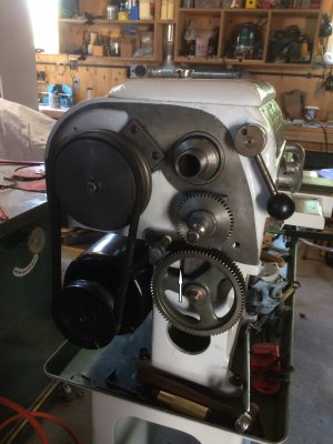
10" LD Utilathe Standard Modern manual.PDF

1) the carriage now moves with some friction, until it gets towards the right side of the bed and then binds. I measured the gap closer to the headstock. Is it possible the bed is worn enough end to end to cause this. I could adjust the gib so as it has more clearance on the one end.

Yes, At the far right end where the tailstock usually sits I found that mine would get a bit tight, I adjusted to allow about 0.002" on the apron gib and the other gib on the carriage I adjusted so that things slid but there was a slight increase in the force as I neared the far right side of the lathe. Typically with the tailstock there you can't really work the carriage much so I thought that would be A-OK. The wear I suspect is more from dragging the carriage lock and having the rear saddle gib too tight as they really only keep the carriage from lifting.

New sight glass: https://www.ebay.com/itm/M-1652-BIJUR-B5944-5-8-OIL-LEVEL-WINDOW-TREE-MACHINE-PART-/303599864677 says may not ship to Canada but that is what you are looking for - Bijur B5944 (that is the updated part number)

2) the cross slide feed now only works if I pull the Feed Selection Plunger and hold it in place. Guess I have to pull the apron back off again.

That is strange, Did you take it all apart? The feed selector just moves the one gear. There is a detent at the back of the shaft that locks the selector in position. It is indicated on the picture with the red arrow pointing to the set screw. Under that should be a spring and ball. The blue arrow is the feed gear for the cross feed and the pink arrow is the drive for the carriage assembly. The middle position you can use the threading handle. The set screw adjusts the tension of the spring on the ball to lock in the feed selector. I played with the adjustment to get it feeling like a solid click into position.
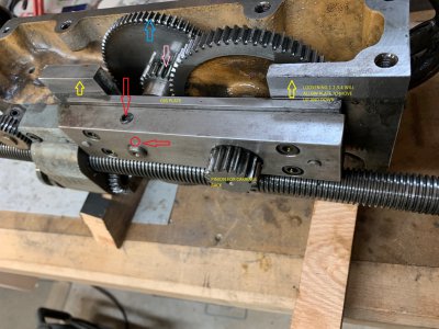

Apron 2.jpg

The chewed up power feed gear - I have the gear cutters to make this part and the part laid out in autoCAD. Just need to get some material and that all important "time to make one" or perhaps two.....LOL
 
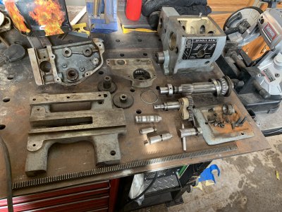
Does anyone have the shaft that operates the chuck of a 9" Standard Modern headstock for forward and reverse assembly? The assembly for the drive train is located under the chuck shaft. The only way I can access the forward and reverses mechanism is by removing the chuck shaft. Has anyone information on shaft removal or repair or tech manual for 9" standard modern or copy of repair manual for a 9" Standard Modern? Or has anyone had the head stock main shaft out of a 9" Standard Modern. Thank you.
 
@Metallathe100 : I have had the entire 9" utilathe torn down to nothing and sent all over North America. The manual is attached.

I can inquire if any of my colleagues has the parts you are looking for. I am checking to see if I have pictures of the part.
 

Attachments

  • standard-modern-utilathe-9-inch-manual.pdf
    2.3 MB · Views: 6
To be clear you are looking for part 42 on page 8 of the manual? The feed reverse lever?

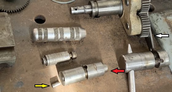
It is a simple part that can be made if one is not located. On the lathe I took apart the dowel pin had been sheared off by careless operation.

Ok here are some pictures for you:

slpit apart lathe 9 inch.JPG

slpit apart lathe 9 inch.jpg

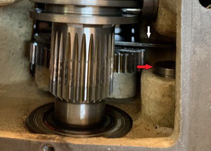
The part with the white arrow is the lever the pin (yellow) fits into. The eccentric rocks the forward and reverse gears into position.

IMG_3111.jpg

If you are lucky I may not have shipped out that part and it is in the scrap bin at home. I cannot check on that though for about 2 weeks as I am away on business. I will ask another guy if he has that part.
 
@Metallathe100 : Parts located for the assembly - the pin is broken off and would need to be replaced - a bit of a PITA but that is what we got...let me know if that is of any help to you.
 
Hey Brent,

I’m the proud new owner of a SM 2000 series 13”. I’ll be picking it up in late August or early Sept. I had been cautioned about separating the headstock from the bed, but in order to get it into the basement I think I am going to want to do so. Any thoughts regarding how easy it will align going back together? How easily did it come apart? And if you find some trouble aligning it let me know.... I have an autocollimator you can borrow.

Cheers,

Derek


Sent from my iPad using Tapatalk
 
@Moderatemixed : hey Derek, it is not that complicated to re-align after pulling things apart. The Standard Moderns have a section that fits the ways at the front of the head stock. there are 2 strong backs that hold the head stock in position (4 bolts). Put the lathe together, take a cut on a large diameter piece (no tailstock hooked up), measure and adjust the back of the lathe. Might require a couple times to dial it in until your cut is 100% across the length. I shimmed the front corner of my Utilathe to get it squared away.

I have the 10 inch utilathe and can pull that sucker apart in record time! After the belt is removed it is just some heavy pieces.

I attached a manual I think is for your model.
 

Attachments

  • standard-modern-1340-manual.pdf
    3.2 MB · Views: 13
Thanks for getting back to me, and fornthe manual. That said the lathe is the Series 2000 13”. This is it......

ad8f3ce92c3ab41c373819f481a3ed9b.png


I’ve just bought a new house, a 2200 sq ft bungalow, and am framing a 22.5 x 14 shop which is why the delay to pick it up (and Covid).

I’ll let you know how the progress goes!

Cheers.

Derek


Sent from my iPhone using Tapatalk
 
Hey Brent.
here is something else maybe you can help me with.
this lathe turns everything on a taper. .oo4 or .oo6” over six inches when held in the three jaw.
it seems the headstock is not square to the bed. Could it be possible?
I have seen YouTube videos of “levelling a lathe”. This one is not bolted to the floor. I‘ve never tried.
not sure where to start.
your thoughts please.
 
@Sacaps :

1) make sure the three jaw is very clean at the mounting surfaces where the D1-3 spindle attaches and all the jaws etc
2) I have my Chucks all stamped so they all go on the same orientation to the headstock (just a 1, 2, 3 punched in the adaptor plate to match the cams)
3) Is there any run out in the 3 jaw to adaptor plate? This needs to be fixed first so it is rotating right on the money
4) if all that is good, take a say, 2" diameter rod with 6" stick out (no tailstock center or anything) and make a few light passes.
5) check the measurements - see what you are getting.
6) You can check your lathe for level, if you have the cast base on the Utilathe, chances are the level aspect will not account for much as the assembly is quite ridged and a 20" between centres lathe with the cast iron bed ways is pretty stiff to twist - but best to be sure.
7) if you are satisfied with level, you can adjust the headstock to square loosening the 2 bolts at the back of the headstock that hold the headstock to the ways.

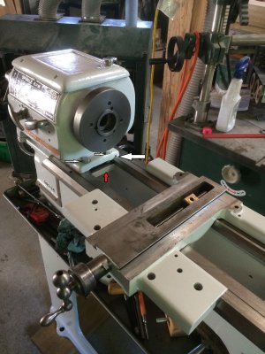
The Utilathe headstock is held in position by 2 strong backs (Clamp plates) and 4 bolts. The front ones are easy access the back ones, not so much... The alignment is also "maintained" by the fit of the bed way at the outside of the lathe. This vee shaped way can cause you grief if it is off the mark with respect to the headstock/bed way alignment. On my lathe I could not get the headstock into position and I did not really want to start grinding or reshaping things. I stoned the vee way and the headstock vee and fit them together. I tightened down the clamp plates, took the practice cuts on a piece of 2" and made adjustments by inserting 0.001" shims under the headstock at the front vee (large arrow in the picture) tightening things down, re-cutting and measuring until I was bang on end to end.

clamp plate.jpg
Clamp plate 2.jpg

I think I added 0.003" to the vee to pull the headstock over just that wee bit. After that I went on to align the tailstock.

Hope that helps?
 
Back
Top