X-Feed Rates on PM lathes

The Jet BDB-1340A lathe seems the same as mine, except the quick change gearbox has been modernized, while mine has the Norton gearbox. The parts list shows all the gear teeth that my manual shows. No tooth count for the cross travel screw.

This link to the Jet manual should work:
content.jettools.com › assets › manuals › 321359A_man_EN.pdf

If not, search Jet BDB-1340A and you should see it.
 
Hi Provincial,

Thanks. The link l did not work, but with a little searching the model number did. For others here is the links I got to work.
https://www.jettools.com/us/en/p/bdb-1340a-belt-drive-bench-lathe/321360A to the lathe, and the manual that it took me to:
https://jpw-assets.s3.amazonaws.com...4818d4c509187f3266a6bfd310_321360a_man_en.pdf

This manual's head stock gear box layout, both outside and for the most part on the inside, looks similar to my PM1440GT. However the gear teeth and sizes numbers are not similar at all. Later I may see if the gear numbers work out to yield the physical layout and thread lead screw motion. From my gear teeth numbers I could get the TPI values, but I could not physically get the gears to shift pass one another! Also, the gears were not in the right physical relationship to each other! The apron gears are only vaguely similar seem to help me to understand my own a little bit more.

Apron: The big handle shaft has a gear on it, but it is not aligned to the Rack nor the worm gear that is shown in Fig. 12-1, Exploded view of the Apron so is not attached directly to the Rack, but is always attached to the Rack via so some gear. It is locked to the rack when either feed mechanism is engaged. However, when the worm gear is connected to the gear box then the Apron will not move via the handle. I initially thought that maybe that big 60T gear was the upper circle that is sticking up (overall box sketch, below the gear layout, shown at the bottom of the figure, but as shaft B it is in the wrong location? However, the letter B on this bottom sketch, is in the right location to engage the Rack!

This worm gear attaches to the FEED drive rod( via the single slot.) So that one turn of the feed rod will cause one turn of the worm gear which then translates to one thread of the which ever gear in the figure attached to it. One might think that this is shaft D and gear item #31. In the parts list this is the only 2mm gear. Gear teeth are suppose to be the same size for matching to another gear so maybe this attaches to the worm. This shaft would not move back and forth so is not the one couple to the FEED lever.

Shaft E with its wide gear #33 would seem to be a coupling between a stationary set of gears on shaft D and the gears that might slight back and forth of Shaft C. However, the draw it below the others in the exploded drawing. I don't know if that has significance.

This would leave shaft C to be the one that moves back and forth with the FEED lever. Also the part #11 appears to have a notch in it to allow the FEED handle to link to the shaft? But I see not spline or key way for any gear to slide along and it would seem somewhat unreasonable that the entire shaft move. The 44T gear #22 might be the one that couples to the Cross Feed lead screw via gear shaft #67 of Fig. 17.1 ?

So the shaft F is a mystery as it is not clear how it fits in. Also the bottom sketch shows it with dashed lines, I think, is this of significance?

So maybe with more time I will figure this out entire gear path out. each gear on a shaft must match to another. This means that if two gears on one shaft that move/shift (between Feed and X-Feed) requires two gears on another to some what match via summed diameters/radii.

However, the gear teeth count and sizes to not match my 1440 so figuring out maybe not really help me with mine much.

Dave L.
 
I figured out what I did wrong with my gear calculations and come up with a cross feed ratio of 1:3.19. I measured an actual 1:3.25. I calculated the ratio after the worm gear since that is the same for both cross and longitudinal feeds. The attached picture is what I believe to be the gear arrangement for my lathe. The manual also shows a table with a 1:2 cross feed ratio, we know that is not correct, so the gears listed might not be accurate as well.
 

Attachments

  • 9D9700CE-DEA0-4846-BE32-31E083680C60.jpeg
    9D9700CE-DEA0-4846-BE32-31E083680C60.jpeg
    104.9 KB · Views: 104
Hi @Ischgl99

Very nice sketch. I need to get you to sketch out my main gear box. I got all of the gears numbers to agree with the final TPI, but I never did get teh physical layout such that the gears could actually shift positions without hitting one another.

I think your apron gear layout must be the same as for the PM1440GT as all of the gear Teeth counts seem to be the same. However, I am having a problem with the 50T gear shaft which shows the end of the shaft to have a M1.5 by 13T, as you note. The problem here is that I had measured the Rack earlier as my manual provided no info on it. When I did this I laid along metal rule against it and it appeared that the tooth repeat pattern occurred at 70T/330mm, which is the same as 7/33, but went out a factor of 10 to get to 70T to be sure. It was a little hard to judge, but I counted the teeth several times. So this gives a pitch of 4.71428 mm/T. This is similar to what I think you noted in your sketch, but did not apply units of mm. This size does not match any metric gear that I am aware of. So I think the diagram for the M1.5 13T shaft holding the 50T gear is incorrect. There is no way that a 1.5mm gear tooth will fit a pitch of 4.714 mm rack pitch??? Maybe it is an English gear tooth size as they are not as straight forward to figure out. I will work on this later.

Obviously the extra digits of my 70/330mm are suspect, but by no more than about 1/10 of a tooth and I really think it is better than this. So ~330/70.1~ 4.708 and 330/69.9 ~4.721. This gear size, that is on the end of the 50T shaft is relevant to a final feed rate. However it appears to be irrelevant to the x-cross feed rate. I just measured by counting 100 turns of the FEED Bar and got 0.931"/100Feed Bar turns = 0.00931. I suppose that I might have missed a little back lash or something so it might have been 0.0094 or so. But it is close enough for now.

If you look at your gear arrangement I think we should be able to predict the actual number. But it is getting pretty late for me to even try. Maybe you want to give it a try and maybe I could also in the light of day. I believe in my turns number as I have both my electronic counter counting and I have set up an old mechanical counter and they agreed on several runs where the total turns was a few hundred. So maybe tomorrow I can make a run at 500 turns of the feed bar, which would represent about 5" of motion. (When I set my gear box to AD and X, then I get 1 spindle turn per 1 Feed bar turn, so I do not actually have to count the revolutions..... just run the lathe slow so that the mechanical counter can keep up. ) Later I can change the gear box so that the feed bar rotations per spindle turn are less and go for even longer runs without running out of travel on the x-feed, and I could do runs for both feed rates.

Dave L.
 
I went a head and made a pass at it. x-Feed rate= {0.1"*(44)/(18*2*13)]/feed bar turn = 0.009401709"/Feed bar turn. Where the 2 is from 44/22. Close to my measurement. Is this what you get?
 
The pitch for a gear rack is simply the module times pi, so 1.5x3.1415=4.71mm for an M1.5 gear rack. That matches taking the circumference of the pitch line of an M1.5 13T gear and dividing by 13 teeth.

For my calculations, I assumed one rotation of the 22T gear tied to the 18T gear that runs on the worm gear. For the cross slide, that would be 22/44 x 44/13 x 0.1” (cross slide screw pitch) = .169” or 4.29mm

For the longitudinal feed, same 1 rotation of the 22T gear, 22/44 x 22/50 x 13 = 2.86 teeth of rotation of the 13T gear. That translates to 2.86 x 4.71mm = 13.47mm travel.

Long/cross is 13.47/4.29=3.14 (I wrote 3.19 above, I must have rounded a number earlier that I didn’t this time).

We can’t blame the difference on a metric or imperial shaft since a 10 TPI shaft is almost exactly 2.5mm pitch, so it doesn’t come close to making it 1:3 instead of 1:3.14. I think the difference is simply that this is as close to 1:3 they can get with common gears in the space they have.
 
Good Morning @Ischgl99
I am back at it. Thanks. I think we are in agreement!:

I like to relate to turns of the Power Feed Bar as this is what comes out of the gear box. On the PM1440GT the setting of A-D, on the factors of 2 knobs, and using the X lever setting results in a 1:1 ratio between the power feed bar turns and the spindle turns. So this results in a x-feed rate that is generated by the spindle turns (for that gear box setting).

X-Feed rate: You used 22/44 x 44/13 x 0.1" = 0.169"/turn to get the X-feed distance of one turn of the 18T shaft. I think to get this to the slotted FEED Bar turns you need to include the ratio of the 18T/22T that are on the 18T shaft. Then you need to include the fact that one rotation of the worm gear represents one Thread on the 18T gear. I collapsed some of this calculation in my previous note and this may have make it less than obvious. My equation from last night is similar to your own with the 1/18 factor put in: {44/(18*2*13)}*0.1" = (1/18)*(22/44)*(44/13)*0.1" ~ (0.169/18)= 0.009401. (Which is in close agreement to what I measured last night!)

Power FEED rate: So in your Power Feed calculation you have 22/44 x 22/50 x 13 = 2.86 teeth of rotation of the Rack, but to get this to the power feed bar I think we have to put in the 1/18 worm gear factor again. So (1/18)(22/44)(22/50)(13)=0.1588888 teeth of the Rack. Then 0.1588888...*1.5*Pi() = 0.74874625 mm or 0.029478" per FEED Bar turn( Z-FEED). The lathe table says it should be 0.0295! So this is in agreement.

The Ratio is in agreement too: 0.029478/ 0.009401 =3.135624.

But note that Pi()= 3.1415926...! Also note dividing the ratio by the Pi() factor yields 0.998031. So all of these number are just a little less than Pi()!! ....and the final result is irrational due to the RACK!

So I think this settles this. We make a pretty good team!

Conclusions (to a ridiculous number of digits, but which pop out of a spread sheet):
X-Feed Rate per power bar turn is: (1/18)*(22/44)*(44/13)*0.1" = 0.00940170940"/bar turn
Power Feed Rate per power bar turn is: (1/18)*(22/44)*(22/50)*(13)*1.5*Pi()/25.4 =0.0294781988"/bar turn
Ratio: 3.13540842

Thanks!!!!

Dave L.
I try to keep things simple, so I only went as far back in the gear train where the driving gear was the same for both the cross and longitudinal feeds. Since the feed shaft and worm are driving the 18T gear, and the 22T gear is attached to that shaft, I could eliminate any unknowns in the worm to calculate the cross to longitudinal ratio. I also rounded some numbers since I felt two digits is plenty accurate for this. Anyways, this has been enlightening and I have a much better understanding of how the apron gears work, so thank you for posting this.
 
Why are you concerned with the feed rate ratio, by counting gear teeth and everything else. Seems like a waste of time. Or I'm missing something. Set the the feed rate in thousands feed per revolution from the machine name plate . Who cares what the ratio may be. Adjust the feed to get the desired finish or chip formation and call it good. If you really need to know, set your rpm, select a feed rate, and measure the travel. Even if the results don't match the name plate, it doesn't matter. The results is what is paramount
 
Hi @aliva

I do not disagree with your vision. I too normally just guess, with some experience, until I find a feed that cuts nice for the current work material. However, @davidpbest provides, in his book, some nice rules about what the feed rate "should be" for a given tool insert and its physical dimensions. That would help a lot with the inital "guess". Read on and you will see why...

However, the our two lathes PM1340GT and PM1440GT we found that the Power Feed rate to Cross Feed rate is NOT 1:2 as the lathe plate and the manual says. And this maybe of value to someone out there. I have also studied the gearing diagrams for the 1440 at length and found it to be in error. When I look at similar older models manuals they are wrong also. So I suspect that it is something that just propagates.

So I wanted to learn more about programing Excel spread sheets with macros which is to say is programing via Visual Basic for Applications, VBA. As a vehicle to learn this I have been trying to write programs which both help me to learn as well as might be useful to someone. My first attempt at this was to write some G-code in a spread sheet and then to use the Macros code to generate a lathe front electronic panel for my VFD conversion. The program allows one to make a round hole, with Keyways and/or flats on it of any size, orientation, and location. You can make as many of these or any variation and place them in space. In addition it does rectangular holes as well as Sub-D connector holes of the most common sizes. Mix and match. Obviously you can also make holes for other applications using the same program. After you describe the number of holes and their other attributes of sizes, locations, orientations, flats etc. then the program automatically will generate the Gcode to make such a panel or other multi-hole device. One can also add other shapes to the program. If you have not seen it, HERE is the thread for the VFD conversion which employees this control front panel for my lathe. And, HERE is the thread for the Excel Gcode generator.

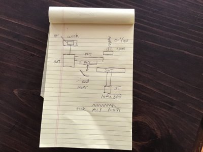
Having finished that to some degree I wanted to continue with my education. So I have been working on an Excel spread sheet which will calculate all of the TPI values that one can obtain with a set of gears for a given lathe. It also provides the TPI values that one would get if he were to use the Power Feed rather than the lead screw and 1/2 Nut. Yes, I know there are reasons one might not want to do this, but when one is desperate he might use it and if so one would like to know the Feed rates to better than one or at most two digits. I have found that what is on the front of the lathes is not very exact! In doing so I decide to list the X-feed rates as well and I did not want to put out something that was wrong. So away I went. The exercise has also allowed @Ischgl99 and I , and hopefully now, others to develop an understand what is inside the apron gear box for these two lathes.

So far my tool calculates the correct TPI for any set of external gears that one might have as well as all of the standard thread sizes. It generates a large table of TPI values (and all other associated distances etc). This can then be searched or just printed as a table for reference. I did these calculations for these two lathes using the external gears that come with them plus a 35T for the 1340. For the simpler 1340GT there are 5122/2 TPI values using the split nut and the same number using the feed bar. A minor fraction of these are redundant, but I will let the user deal with that. The 1440GT has a different and more complex gear box and so it has 6144 using the split nut and 1536 using the Feed bar. I have a program that will search this list and find all of the TPI values around a value of your choice.

Now I am trying to make the spread sheet as user friendly as I would want it to be. After that I will post it for everyone to have and if someone wants to add another lathe that would be great. I might even do it for them if I know what it is and how its gears etc are configured.

I do not know what lathe you have, but would you be interested in getting a table, spread sheet, etc. ? With or without exact feed rates!


Dave L.
 
Back
Top