- Joined
- May 15, 2021
- Messages
- 6
I recently upgraded to a G0602Z from literally the cheapest 7x14 I could find on fleabay ($410 USD) and the differences so far are.... vast.
On the 7x14 I put a 750w sewing servo, re-milled the underside of the bed ways, rebuilt the tailstock foot, trued the tailstock casting, trued the saddle gib mounts, built new saddle gibs, replaced the compound with a solid block of A36, and added the Clough42 ELS.
My mill (WMD25VB from the PM OEM for the 25MV) I have become completely enamored with the BLDC drive, so I found a controller and motor combo from overseas to retrofit an 1100W BLDC in place of the heinously noisy 1PH AC motor on the 602. I might also replace the cogged back-drive belt with a j-profile serpentine belt just for some extra quiet. The ELS will move to the 0602 as well, probably utilizing a 2:1 gearbox ratio as fabrikator has shown on here.
I searched high and low for headstock lubrication because Grizzly says oil, some threads on CNC sites from the early 2010's say to use the grease the bearings shipped in, others with replacement bearings say grease, SKF lubeselect for bearings shows a whole other profile for lathe spindles (angular contact BB w/ LGTL2 grease) and it's all very confusing. For now I have decided that since the ball oilers are there and are a potential ingress for contaminants, it would be best to just keep oil in there so the contaminants can hopefully be flushed out. I come from a motorcycle, automotive, firearm, 3d printing, and mech-E background so my instinct is that a tapered roller should have grease and get re-packed every few years if not sealed. Others have mentioned oil weeping from the bearings which I have not seen happen on my 602. It was incredibly difficult to even get oil to go into the oilers This made me think there was a bunch of garbage in there since an open TRB should weep oil from behind a flimsy painted steel cover.
I noticed others mentioning swarf, grinding dust, etc in the bearings from factory so my thinking was this:
- Use a hydraulic oiler to 'flush' the bearings with a cheap 30-50WW motorcycle oil (fewer friction additives safe for wet clutches and typ. non-detergent)
- Flush the 'improper' oil with mfg-recommended ISO32 (Hey, Vactra 1 is ISO32, that's convenient, and gearbox says ISO68 which is vactra 2 though to be honest I am considering just using vactra 2 on everything since the only real difference is viscosity at 40C and if I hit the flash point of ANY vactra then my machine has serious problems anyway.)
I already tried the flush on the front (facing chuck) bearing and it took a lot of hydraulic pressure at first but eventually began to puke out a blackish-grey goop. I kept flushing (and it got noticeably easier) until clean oil was ejected. I think I did okay, but wanted to get HM's take before I continue with the rear bearing.
On a sidenote, I am trying to figure out the lowest-profile way of leveling the lathe bed feet. I need my machines to be portable (eventually) because I live in a small townhome, so it lives on a 44" US General toolchest with a 1.5" solid birch butcher block top with the chest on carrymaster knockoff leveling casters. My machines live in my3rd bedr-- carpeted machine shop and I'm 5'10". Direct on the butcher block, the lathe carriage handwheel is slightly below 90* elbow angle and the cross-slide handwheel is slightly above a 90* elbow which feels nice (miles ahead of my 34" wood bench the 7x14 occupies which resulted in back pain rather quickly) but I can feel waviness in the butcher block top with my fingers so I know this will need some sort of feet between the lathe and benchtop to achieve level. I have seen several different solutions involving jacking screws either on pads made to the size of the feet (above chip pan) or on spans going front to back (below chip pan).
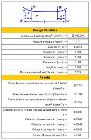
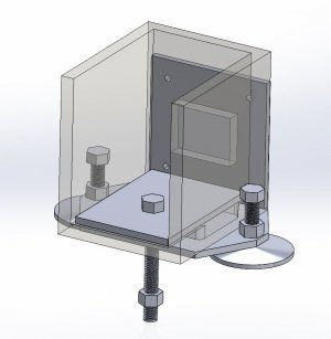
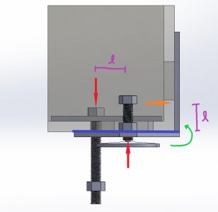
Attached is a section view of what I think a low profile mount might look like using 6" wide by 8" long 1/4" steel. Bottom plate is threaded 1/2-20 at the front/back with jack screws and lock nuts. Bolts have a 3mm stud turned from the head which goes through the top plate (beneath chip pan) to keep them aligned. Center is 1/2-13 through both plates and top/cabinet only snug-ish. Would 1/4" plate be strong enough?
On the 7x14 I put a 750w sewing servo, re-milled the underside of the bed ways, rebuilt the tailstock foot, trued the tailstock casting, trued the saddle gib mounts, built new saddle gibs, replaced the compound with a solid block of A36, and added the Clough42 ELS.
My mill (WMD25VB from the PM OEM for the 25MV) I have become completely enamored with the BLDC drive, so I found a controller and motor combo from overseas to retrofit an 1100W BLDC in place of the heinously noisy 1PH AC motor on the 602. I might also replace the cogged back-drive belt with a j-profile serpentine belt just for some extra quiet. The ELS will move to the 0602 as well, probably utilizing a 2:1 gearbox ratio as fabrikator has shown on here.
I searched high and low for headstock lubrication because Grizzly says oil, some threads on CNC sites from the early 2010's say to use the grease the bearings shipped in, others with replacement bearings say grease, SKF lubeselect for bearings shows a whole other profile for lathe spindles (angular contact BB w/ LGTL2 grease) and it's all very confusing. For now I have decided that since the ball oilers are there and are a potential ingress for contaminants, it would be best to just keep oil in there so the contaminants can hopefully be flushed out. I come from a motorcycle, automotive, firearm, 3d printing, and mech-E background so my instinct is that a tapered roller should have grease and get re-packed every few years if not sealed. Others have mentioned oil weeping from the bearings which I have not seen happen on my 602. It was incredibly difficult to even get oil to go into the oilers This made me think there was a bunch of garbage in there since an open TRB should weep oil from behind a flimsy painted steel cover.
I noticed others mentioning swarf, grinding dust, etc in the bearings from factory so my thinking was this:
- Use a hydraulic oiler to 'flush' the bearings with a cheap 30-50WW motorcycle oil (fewer friction additives safe for wet clutches and typ. non-detergent)
- Flush the 'improper' oil with mfg-recommended ISO32 (Hey, Vactra 1 is ISO32, that's convenient, and gearbox says ISO68 which is vactra 2 though to be honest I am considering just using vactra 2 on everything since the only real difference is viscosity at 40C and if I hit the flash point of ANY vactra then my machine has serious problems anyway.)
I already tried the flush on the front (facing chuck) bearing and it took a lot of hydraulic pressure at first but eventually began to puke out a blackish-grey goop. I kept flushing (and it got noticeably easier) until clean oil was ejected. I think I did okay, but wanted to get HM's take before I continue with the rear bearing.
On a sidenote, I am trying to figure out the lowest-profile way of leveling the lathe bed feet. I need my machines to be portable (eventually) because I live in a small townhome, so it lives on a 44" US General toolchest with a 1.5" solid birch butcher block top with the chest on carrymaster knockoff leveling casters. My machines live in my
Attached is a section view of what I think a low profile mount might look like using 6" wide by 8" long 1/4" steel. Bottom plate is threaded 1/2-20 at the front/back with jack screws and lock nuts. Bolts have a 3mm stud turned from the head which goes through the top plate (beneath chip pan) to keep them aligned. Center is 1/2-13 through both plates and top/cabinet only snug-ish. Would 1/4" plate be strong enough?