Wiring my PM 727v spindle motor to KBSI-240d board HELP

Cad cam man

Registered
Registered
Joined
Mar 5, 2021
Messages
55
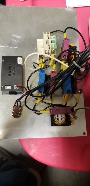
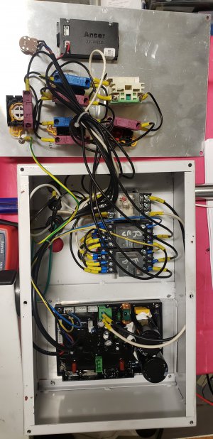
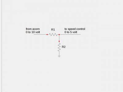
Hey guys I have some questions on wiring my spindle motor to the KBSI-240d and Centroid Acorn board . I have a PM727V the spindle board has been potted and I have tracked down the Forward and the Reverse wires along with the Common . I need to find out which wires are the 0-10v wires from the pot . Is there a sure fire way to check to see what wire is the + ,_ and the wiper on the pot? I have never done any wiring dealing with pots . I know that the acorn board needs the 0 and 10 v wire does any one have any wiring schematics that has this on it ? Like i said the board has been potted so I dont know what wires are what
 
Use your dc voltmeter- measure from the common to each of the three pot terminals. Usually the middle terminal on pots is the variable pin or wiper, you should see a variable voltage there. The other two terminals will be +10 and 0 volts
-Mark
The pot is present isn't it? Or is there no pot, just wires?
 
The pot is there yes .. I will check the wires this afternoon . Thanks for the fast reply
 
The 0 volt pin may actually have a small voltage instead of zero on some systems, but it should be lower than the opposite pin by several volts
-M
 
Use your dc voltmeter- measure from the common to each of the three pot terminals. Usually the middle terminal on pots is the variable pin or wiper, you should see a variable voltage there. The other two terminals will be +10 and 0 volts
-Mark
The pot is present isn't it? Or is there no pot, just wires?
Mark,
I have measured all 3 wires with the pot turned down i get 5 volts on the blue wire and 0 on brown and 0 on black . When I turn the pot to full on I get 5 volts on blue , 5 volts on brown and 0 volts on black . So how do I determine what is my out and what is my ground .
 

Attachments

  • 16212961669785693938219753274638.jpg
    16212961669785693938219753274638.jpg
    923.8 KB · Views: 73
  • 16212961933542576323665808582413.jpg
    16212961933542576323665808582413.jpg
    1.1 MB · Views: 74
Looks like black is ground and brown is the output. Put your meter negative on black and positive on brown and turn the pot, the voltage should vary from 0 to 5 on the brown as the pot is turned.
 
Blue is high +5V, brown is the sweep and black is the 0V or negative. A bit ironic, typically brown is positive and blue is 0V in Asian and EU machines.
 
Looks like black is ground and brown is the output. Put your meter negative on black and positive on brown and turn the pot, the voltage should vary from 0 to 5 on the brown as the pot is turned.
Ptrotter yes I did as you described negative on black and positive on brown and turned the pot and the voltage varies
 
If your acorn board outputs a 0 to 10 volt signal you may need to divide it down to a 0 to 5 volt signal like this:
The two resistors would have the same value, perhaps 1k or 2k ohm
Check the value of the pot it may be printed on it or you could disconnect it and measure it, it's probably in the range of 5k
 

Attachments

  • divider1a.jpeg
    divider1a.jpeg
    31.7 KB · Views: 88
Last edited:
While on this subject what size wire should I use to run the fwd , rev, com, to the relay board from the spindle control board and 0 and 5 volt from the spindle control board(pot) over to the Acorn board ???
 
Back
Top