Wiring a new drum switch to my original MW motor

zayd

Registered
Registered
Joined
May 17, 2020
Messages
13
Hello, folks.

I'm hoping some of the electrical specialists here can help me out. I'm fairly clueless on motor wiring, so this is basically the last thing between me and getting this Logan/MW 10x24 up and running.

A little background: I picked up this Logan/Montgomery Wards lathe (I believe it's the 84TLC-2130) from a smaller machine shop last year. It had clearly been stored for a long time, but was fairly complete and largely original. I completely disassembled it, cleaned everything, assembled it, lubed everything that needed it, and leveled the lathe. It's back together now, but I've saved the wiring (my nemesis) for last.

It came with the original, 1/2hp dual voltage 1ph Wards motor, capacitor start. Here's the best photo I could get of the faded motor plate:
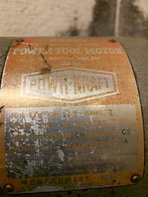
mwmotor.jpg

There are six leads coming out of the motor, all red wires with original labels. As best as I could tell and assuming no labels fell off, this is how they're labeled: 2, C 5, J 6, 7, 8, and E.

It was missing the front half of the original switch, so I bought a new Dayton 2X440A reversing drum switch to use instead. Here's the diagram on the inside of the switch cover:
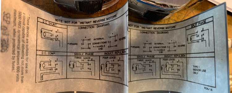
switchdiagram.jpg

I don't believe the original Logan wiring instructions are a lot of help since this is not an original switch, but it is here.

http://lathe.com/wiring_diagrams.htm

(I think I have the "1105" motor on the right side of the page).

The bottom line is that I'd like to wire it 110V, but I'm lost on how to interpret these diagrams. Any help would be fantastic.

Thank you!

Zayd
 
Last edited by a moderator:
Does it say anywhere on the motor "swap wires so and so to reverse"? If not we need to do a bit of testing with a multimeter
-Mark
 
Hi, Mark. I did not find those instructions on the motor like I'd typically see. I checked under the peckerhead cover as well. I'm handy enough with a multimeter, so I'm good with that approach. Thanks.
 
Hello, folks.

I'm hoping some of the electrical specialists here can help me out. I'm fairly clueless on motor wiring, so this is basically the last thing between me and getting this Logan/MW 10x24 up and running.

A little background: I picked up this Logan/Montgomery Wards lathe (I believe it's the 84TLC-2130) from a smaller machine shop last year. It had clearly been stored for a long time, but was fairly complete and largely original. I completely disassembled it, cleaned everything, assembled it, lubed everything that needed it, and leveled the lathe. It's back together now, but I've saved the wiring (my nemesis) for last.

It came with the original, 1/2hp dual voltage 1ph Wards motor, capacitor start. Here's the best photo I could get of the faded motor plate:

View attachment 336627

There are six leads coming out of the motor, all red wires with original labels. As best as I could tell and assuming no labels fell off, this is how they're labeled: 2, C 5, J 6, 7, 8, and E.

It was missing the front half of the original switch, so I bought a new Dayton 2X440A reversing drum switch to use instead. Here's the diagram on the inside of the switch cover:

View attachment 336628

I don't believe the original Logan wiring instructions are a lot of help since this is not an original switch, but it is here (I think I have the "1105" motor on the right side of the page).

The bottom line is that I'd like to wire it 110V, but I'm lost on how to interpret these diagrams. Any help would be fantastic.

Thank you!

Zayd


Welcome to the group zayd. Sorry, I can't help with the wiring, but we have plenty of folks here that can. We would like to
see some pics of your lathe when you can get to it.
 
****************************
I don't believe the original Logan wiring instructions are a lot of help since this is not an original switch, but it is here (I think I have the "1105" motor on the right side of the page).
*********************************

Try again to show the original hookup instructions. They did not show up in your post.
 
Welcome to the group zayd. Sorry, I can't help with the wiring, but we have plenty of folks here that can. We would like to
see some pics of your lathe when you can get to it.

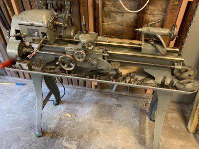
Thanks! Forgive the hypocrisy; I'm also usually quick to look for photos. Here's a hasty one. The chip pan was a later find. There are also a few bits not pictured, like the 3- and 4-jaw chucks, steady rest, and a couple other little things. Overall, I'm only short a parting tool holder and some good HSS or carbide bits.

IMG_6085.jpg
 
Incidentally, with all of the different drum switches that are or were available, 98% of them are built one or the other of two ways.

The link to the Logan site was corrupted but I think that I fixed it. For some reason that I didn't look into, the Attachment 336645 is either missing or corrupt. But if you hover your mouse pointer over the URL now shown, it brings up the "Motor and Switch Wiring Diagrams" on the Logan site.

I think that you are probably correct in saying that your motor is the 1105. But unfortunately, as the motor that you have is not labeled the same as the 1105, you are going to have to do some exploring with the Ohmmeter. I will write that up next.
 
Thanks! Forgive the hypocrisy; I'm also usually quick to look for photos. Here's a hasty one. The chip pan was a later find. There are also a few bits not pictured, like the 3- and 4-jaw chucks, steady rest, and a couple other little things. Overall, I'm only short a parting tool holder and some good HSS or carbide bits.

View attachment 336646

Nice looking lathe. Any idea what the bracket on the carriage was for?
 
First, make a safety check. I don't know what kind of ohmmeter you have so if any of the following steps can't be done, just skip them.

Set the +/- switch to +
Set the mode to Ohms. Set the range to the highest value that the meter has, such as R X 10K
Connect the negative meter lead to the frame of the motor.
Momentarily touch the positive lead to the motor frame. Reading should be zero or near it.
Connect the positive lead to each of the 6 wires, one at a time. No wire should show less than Infinity. If any do, note the wire number and resistance reading and proceed to the next wire. When finished with all 6, if any showed continuity to the frame, stop and report the results. If not, proceed.

Connect the negative meter lead to 2. Connect the positive lead to the other wires, one at a time. Only one wire should show less than Infinity. Note the wire number and resistance reading. If necessary, temporarily switch the ohmmeter to a lower range in order to get an accurate reading. Switch it back to the highest range before proceeding to the next wire. If a second wire also showed continuity to 2, record that and the resistance. Note that one pair of wires (the START circuit) should show momentary resistance between the wires and return to infinity. If you find such a pair but it does not return to infinity, you have a bad start capacitor. Note that but carry on with the test. When all have been checked for continuity to 2, move the negative lead to C5 (unless it was the one connected to 2, in which case, skip it). Proceed to check and record the resistance between each of the remaining wires. Report results here.
 
Back
Top