Which Way to Turn the Rotary Table?

oskar

Registered
Registered
Joined
Nov 24, 2013
Messages
254
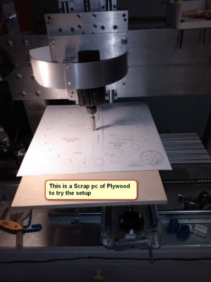
Almost zero experience with a mill but I thought perhaps it will be easier to do this cut on the mill than using my router. Besides, if this cut is successful then I can do the required reaming cuts on the inside of this wheel which has a few more smaller circles.

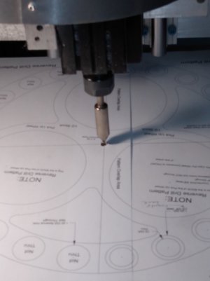
I’m making a wooden clock as a hobby and the wheel shown here is a 12.5” OD wheel which I will cut on a Baltic Birch plywood. I will be using a 1/8” 2 flute bit and will cut the 1/2” ply in 3-4 steps. The ply is secured on my 4” Rotary Table with double sided tape in 4 places and I hope it will stay there.

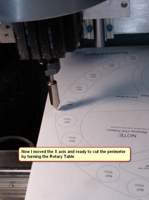
My question is which way do I turn the Rotary Table, CW or CCW?

Thanks
 

Attachments

  • 2 Pickup Wheel1.jpg
    2 Pickup Wheel1.jpg
    119.5 KB · Views: 29
  • 2A Pickup Wheel.jpg
    2A Pickup Wheel.jpg
    71.9 KB · Views: 24
  • 2B Pickup Wheel1.jpg
    2B Pickup Wheel1.jpg
    102.2 KB · Views: 27
As long as you have taken out the backlash it should be fine to turn it either way. On mine the graduations are designed to count up when you turn it CW but the overall design works either way, just like the feed on your milling table, works both ways. Looks like a great project, all the best getting it completed.
 
I always turn in one direction. Either direction works but I always come at the final position from the same direction. If I overshoot, then I reverse far enough to absorb any backlash/lost motion and advance to my final position.
 
For positioning using the dials, all that is required is you turn in one direction only. If you overshoot, backup 2× more than your backlash and go forward again. Again the direction does not matter as long as you go in only one direction.

For milling you are going to be taking light cuts anyway, but try to avoid climb milling until the finish pass.
 
My thanks to all, of course the final setup will include the allowance for the cutter radius
 
Milling thin plywood isn't going to generate much (if any) forces, compared to milling steel or aluminum. In this case it probably isn't going to be an issue no matter what you're doing. Aluminum, steel.....different story.
 
Ah, wooden gear clocks... my nemesis. I started but cutting the gears by hand... too inaccurate. Paid someone to cut them with a CNC router, very messy edges. Looked into laser cutting, but at ~$700 for one set, no. Wondered if making one with a 3D printer would work. Looks like it will, though I'll be first to admit that it would never have the warmth of wood, but we'll see.
 
Ah, wooden gear clocks... my nemesis. I started but cutting the gears by hand... too inaccurate. Paid someone to cut them with a CNC router, very messy edges. Looked into laser cutting, but at ~$700 for one set, no. Wondered if making one with a 3D printer would work. Looks like it will, though I'll be first to admit that it would never have the warmth of wood, but we'll see.
Actually cutting the wooden gears is the easiest. I use a modified coping saw which accepts scroll saw blades and it goes very well and clean. Time consuming but after all its a hobby project
 

Attachments

  • 21I Cutting Coping Saw.JPG
    21I Cutting Coping Saw.JPG
    205 KB · Views: 15
Just out of curiosity, why don't you just mill the parts instead of hand cutting them?
 
Back
Top