Where to start? Thinking of converting my mills and lathes to CNC.

Thanks for those settings Steve. The diagrams you posted are easy enough to understand so I don't think I'll have any problems following them.

The only hold up at this time is going to be the voltage converters. I'm hoping they get here soon so I can see how big they are. That will determine where they get mounted on the mounting plate and also where the attached wires will be routed.
 
Looks like the edit function is back so I added the parts from CNC4PC to the consolidated parts list in post #64 above.

I've been getting more of the wiring done today and should have it finished by tomorrow. Except for the 12V & 5V voltage converters which haven't arrived yet.

I'll start making the plug panel for the motherboard tray after that. I dissected an old power supply for the 110V AC power cord plug socket and I'll be adding that into the motherboard tray back panel as well (if it fits that is). I'll use some of the extra 16Ga steel I have left over from making the main panel mount. Here's a quick MS paint rendition of the back panel layout showing what I have in mind.
CNCenclosurebackpanellayout.jpg
 
I try to keep ac away from dc every chance i get because of interference
if you have the room maybe moving the plug away from the motor wires is advisable if not use shield wire on everything in the area its easier to do it first than to try to find a problem if your having one. this system works on 5v but small stray voltages can cause crazy things to happen. an ac wire next to another wire will cause induction in the other wire producing unwanted voltage and or signal interferance to the controllers.
steve
 
The AC power plug socket has choke loops on all three of the wires and I'm tying all the motor cable shielding wires to the case to ground them. If you don't think that will be good enough I can always move the motor plugs to the other side of the DB25 plug. However it will be a lot more crowded on that side of the panel if I do. I'm not sure if I will have enough room to fit all 4 motor plugs there. If not, I could put 2 on either side of the DB25 plug, with the top two as far away from the AC plug as possible.
 
if the motor wires are shielded you should be ok
steve
 
Thanks Steve. That's good to know.

The 12V and 5V DC voltage converters both arrived in the mail today so I should have everything I need to finish up the driver enclosure box now.
 
here is an xml file to start testing your motors
unzip the file and copy it to c:\mach3 it is named "gomopar440.xml"
when you start mach3 chose it to test you mill
other things will have to be set to your needs as you get used to using your mill.
if you havent done it already when you install mach3 reboot the pc before trying to run your equipment or it wont work right
they will probably run faster but i set them to 40ipm for testing you will have to tune them once mounted on the mill.
40ipm is pretty fast to start learning
the estop is disabled in the xml file for testing and should be enabled in setup and set to the correct pin number.
if for some reason you need to stop all movement hit the space bar or escape key and the motors will stop.
when you install your e-stop hook one terminal to ground pin24 on the breakout board, and the other to pin 10 on the breakout board.
i'll tell you how to enable it to work once your done testing your other wiring so there is no conflict but get it working before trying your mill.
cnc is dangerous so these things i'm helping you with are guide lines and should all be treated with the possible chance of harming yourself so be careful its scary when your trying one thing and the mill is doing something else. i'm not there and there are a lot of settings so i have no way of knowing your doing this right. i have to say i'm not responsible for anything your doing just trying to advise. yada yada yada
this file should be set close to the correct pulse per inch for your ballscrews we can get it perfect once running.
steve
 

Attachments

  • gomopar440.zip
    30.1 KB · Views: 4
Well, My brother wanted to help get the dirt bikes running while he was here instead so the CNC project got put on the back burner for a couple of days. He flew out yesterday so I'm back working on the electrical stuff.

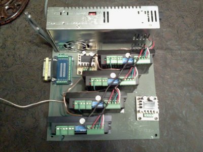
I've figured out where I want the voltage converters and I have them bolted to the base plate now.
2013-03-14223411.jpg

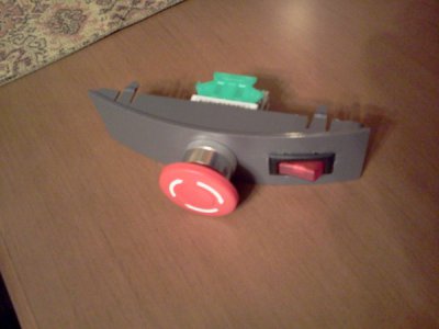
I left room for the fans but still need to make some mounting brackets for them out of some pieces of 1/2" aluminum 90* angle with some 1/2" flat aluminum for top supports. While I was looking over the other parts I went ahead and mounted the E-stop switch and a 110V lighted rocker switch for turning it on.
2013-03-14223300.jpg
 
I don't know if an X3 kit would work on an X2, but Grizzly has kits in their catalog with everything but the computer for $2600 (T25435) that seem quite reasonable to me (less than an hour total instal time, not much more $ than do it yourself approaches).

Sorry, didn't read through all the posts to see that you're well on your way!
 
I've got the enclosure plate almost finished as far as I can go for now with the wiring shown in the diagram above. I just need to figure out how to wire the power switch and the E-stop switch next.

I'll also need to dig out my multimeter and replace the batteries on it so I can check the power supply output voltage and also verify the correct voltage is coming out of the 12V and 5V voltage converters.
 
Back
Top