When the surface plate is just too small ..

With load fee etc, I was able to acquire a 3'x4' surface plate for less than US $200. I'm sure I'll spend more than twice that having it calibrated. I think there is an aspect of intellectual pursuit to your method, rather than just purely pragmatic progress.
Wow! A real score! Would that be granite type?
Mine was acquired as a freebie, because it had been replaced by a new, larger one, and it had stood around for a couple of years unused. My pals even delivered it for me :)
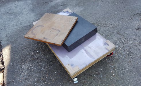
GraniteBlock3.jpg

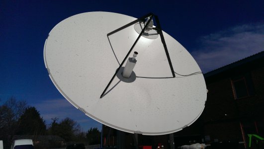
In the work I did at the time, I would have the surfaces of satellite Earth Station tracking dishes tested. The surface would be a optically shaped not-quite parabola polynomial in carbon fibre. It is quite difficult to get a 6.1m or 7.3 metre diameter Cassegrain dish, with its subreflector optics surfaces made and positioned all to within 0.25mm (0.0098 inch). The measure method was photogrammetry, where the surfaces are covered in accurately made little circular decals, and various bar-codes. Also, an invar bar covered in barcodes is placed in the dish. A camera on a pole is used to take a series of images that are then processed by the software, adjusted to get all the corresponding decals to register. The software is then capable of fitting the whole lot in comparison to a CAD model, and publishing coloured contour plots of deviations. One can see immediately where the departures are or where the cure in the mold had a distortion.
IMAG1075a.jpg

You can look up the technique, and I am sure there will be stuff on YouTube. This stuff is widely used in the aerospace industry, and the software is available. There are even free open source versions, and various ways of calibrating digital cameras. You can, of course, buy the whole kit, but it comes expensive. Applied to smaller stuff, like say a thing like a lathe bed, I just don't know the kind of accuracy it is capable of. I had a hard enough time getting the work to under 0.25mm (but the thing was huge)! The measure kit seemed accurate to better than 0.1mm (0.004"), even on that scale. The servo kit behind has resolution to point to within about 300 milli arc-seconds. It has to find a moving target satellite position accurately, but also at an exact celestial time.

The clinometers are set up on a granite surface plate, but that is only good enough for an approximate start point. They are then set to track a sunspot, to discover construction leveling correction and North axis. Finally, known satellites are tracked, and the numbers adjusted to achieve true horizon and zenith calibration.

From what I learned among the guys who do this, I do suspect that traditional scraping just might be augmented by some newer tools, and different technology techniques. Now away from the rat-race, I am quite happy to scrape away on my own stuff, with some reference to Connelly, but not exclusively, when I want to try something of my own.
 
Last edited:
Wow! A real score! Would that be granite type?
Yes, 6” thick. Stand included but I may make a new one with wheels, of course 3 point support. FWIW, 4’ x 3’ x 6” of grante is just about 1000lbs.

Those satellite dishes and barcodes are an interesting technology. Thanks for sharing.
 
I just saw this and my name was mentioned. I am to tired to respond in full now. I do use the book as a reference all over the net and in my classes them to time time plus I sell them on ebay . I have a lot of respect for it as much in valuable but much isn't. I don't know any professional rebuilder the needs it, but rookies do. Lance Baltzley and Adam Booth (friends and students) have done You Tube shows on YT and they don't use it and teach how to lap plates.
My Dad met Connelly. I invited Connelly to lunch once but has had onsets of dementia then, so we never met in person, just talked briefly on the phone. This was approx. 45 years ago. good night.
Thanks Richard.
Citing you in the context of a conversation on the Connelly publication is, I hope, taken as something of an honourable mention.
 
Last edited:
That is a very interesting idea to try to use tech to replace a surface plate. My guess is you will spend a lot more money and work harder for the same result? How would photogammetry be applied to such a precise surface? Would a digital camera have enough resolution? What about something like interferometry? Maybe that would be too sensitive?
 
That is a very interesting idea to try to use tech to replace a surface plate. My guess is you will spend a lot more money and work harder for the same result? How would photogammetry be applied to such a precise surface? Would a digital camera have enough resolution? What about something like interferometry? Maybe that would be too sensitive?
As I understand it, get close enough with the right lens, enough to get images from different angles, the limit is probably in wavelengths of light. Some have experimented with blue light, and microscope cameras. The resolution is decided by the images you take. I have not explored the trick extensively, being that I designed the surface, but did not have to make it. I did see one of the guys scan a real car, with it's front door taken off, and overlay a CAD wireframe image onto it, to exactly design a new hinge location arrangement. It included the animation of the door being swung open.

You are right in that a main aim is to use software and optical tricks to dispense with the need for a physical reference surface. To stay with the reference flat for a minute, it is already possible to use a CNC router-style assembly, fitted with an electronic transducer indicator, to measure over a surface plate, making a subtraction mapping calibration array, to effectively "zero out" all the deviations in the machine. The structure might have all sorts of inaccuracies, but the quality of the reference surface is in effect "captured" in the stored numbers of the calibration map. From then on, accurate measurements can be taken on a real object put under it. This method was explained to me by a work-experience student. It is the way software is used to calibrate all sorts of stuff, from the noise in an astronomical image dark current, to a full scale metrology machine.

Take it one step further, using the machine to measure it's own ups and downs by using a mounted mirror, and calibrating from a laser interferometry arrangement with an optical flat. The calibration mapping gets stored as before. Quite novel was the idea of measuring a surface with the machine, and then printing the result contours onto the surface with a mounted robotic inkjet printer head. Predictably, all those guys were mad keen on CNC, and 3D printing, and knew all about ball-screws. I freely admit, I was getting out of my depth!
 
Last edited:
Much (most) of the discussion is beyond me. I know enough to follow but nowhere near the skill, or even desire, to pursue the matter. My post is only in response to the original question of trueing a straightedge to a surface plate. In the history of things, it actually is the surface plate trued to a straightedge.

The origin of a straight edge is well known with the use of three "bars" that are worked together to an "exact" match. How close the word "exact" is to true is an exercise for the user. In fiber optics work, devices are measured in microns. To make that level of accuracy over a three foot distance is a matter of the type of marking "fluid" used. Nothing more except a lot of scraping.

.
 
Here is an interesting / educational magazine article about Granite Plates and testers. Repeat-a-meter.
I am going to draw a picture like Graham did teaching you how to scrape long parts on a short part, be it a surface plate or a straight-edge. Tonight)
All these "new methods" are not new idea's as they have been done for years. People are always trying to re-invent the wheel. What I teach was passed down from Journeymen Scraping masters for generations. I didn't just dream them up or guess at them. Master scrapers have passed them down for years. Don't you think all these new idea's have been thought of and tried hundreds of times before? What has changed in test devices. I did a race years ago at General Motors. They had a 20' tall surface broach laying on it's back and I raced a new Hamar laser and my King-Way level and Starrett 199 level. The test was to see who could level the machine to .0002" / 12" the fastest. I won the race as setting up the laser and letting it warm up to use took 20 min. longer then me doing it the old fashion way.
 
Richard-That is a most interesting and educational article! After reading it twice, I am still fuzzy on the difference between flatness and repeatability? What am I missing? It it because flatness is indicated at single points and repeatability is based on a larger area of the plate?
 
Richard-That is a most interesting and educational article! After reading it twice, I am still fuzzy on the difference between flatness and repeatability? What am I missing? It it because flatness is indicated at single points and repeatability is based on a larger area of the plate?
Watch this and you will understand vs. me telling you. Tom Lipton is also one of my scraping students.
 
Back
Top