When delicate stuff has to be done with something HEAVY ?

Well let's see,
use an overhead piece of unistrut spanning a couple rafters,
get a unistrut trolley: https://www.amazon.com/Genuine-Unistrut-P2950-EG-Trolley-Assembly/dp/B00KN9UA0S
hang a block and tackle from the trolley to a balance beam.
Use the 4:1 balance beam so your total load is ~50kg.
That would give you a broad range of movement, and fine control over a small range for actually printing.
 
Last edited:
Well let's see,
use an overhead piece of unistrut spanning a couple rafters,
get a unistrut trolley: https://www.amazon.com/Genuine-Unistrut-P2950-EG-Trolley-Assembly/dp/B00KN9UA0S
hang a block and tackle from the trolley to a balance beam.
Use the 4:1 balance beam so your total load is ~50kg.
That would give you a broad range of movement, and fine control over a small range for actually printing.
Yes indeed - that is pretty much what I was describing in post #26.

My little shop is 3.65m (12ft) wide across the inside, with over-designed joists. I made them floor joists instead of ceiling joists (so I could stack stuff up there). A more general mini-gantry hoist has been suggested, hanging small RSJs each side along the walls, and a somewhat fatter moving RSJ across, riding on bearing runner plates. These beam trolly things can be bought, but are often made as a DIY project.

Not that I am contemplating anything as mighty as as the project by April Wilkerson, but it does illustrate the principle. Just imagine it scaled down to a single fixed Unistrut hung across a few (say 4) of the oversized ceiling joists. Their trolly plate is seen at 6:06 in the video. There are plenty other videos about beam trolley hoists projects.

Unlike a full moving cross-beam (gantry?), designed to access the whole shop area, the much more modest arrangement is to use a single short beam hung on the joists, long enough to get over the work area, starting from one end over the floor. One dimensional trolly movement along the fixed beam is what you have. The beam does not have to be stout enough to free span across the shop. It just gets fixed at 4 points 40cm apart.

RSJ beams are more to handle bigger loads, like a 1/2 ton and up. In my case, a Unistrut is cheap, fast, and perfectly good for a little 50-80Kg load. I think I will try the scaled-down Unistrut version first. It may be all I ever need. As it happens, I already have some Unitstrut and hanger brackets stashed in the garage. I would not be using chains.

DIY Garage Gantry with Chain Hoist
 
Last edited:
Yes indeed - that is pretty much what I was describing in post #26.

My little shop is 3.65m (12ft) wide across the inside, with over-designed joists. I made them floor joists instead of ceiling joists (so I could stack stuff up there). A more general mini-gantry hoist has been suggested, hanging small RSJs each side along the walls, and a somewhat fatter moving RSJ across, riding on bearing runner plates. These beam trolly things can be bought, but are often made as a DIY project.

Not that I am contemplating anything as mighty as as the project by April Wilkerson, but it does illustrate the principle. Just imagine it scaled down to a single fixed Unistrut hung across a few (say 4) of the oversized ceiling joists. Their trolly plate is seen at 6:06 in the video. There are plenty other videos about beam trolley hoists projects.

Unlike a full moving cross-beam (gantry?), designed to access the whole shop area, the much more modest arrangement is to use a single short beam hung on the joists, long enough to get over the work area, starting from one end over the floor. One dimensional trolly movement along the fixed beam is what you have. The beam does not have to be stout enough to free span across the shop. It just gets fixed at 4 points 40cm apart.

RSJ beams are more to handle bigger loads, like a 1/2 ton and up. In my case, a Unistrut is cheap, fast, and perfectly good for a little 50-80Kg load. I think I will try the scaled-down Unistrut version first. It may be all I ever need. As it happens, I already have some Unitstrut and hanger brackets stashed in the garage. I would not be using chains.

DIY Garage Gantry with Chain Hoist
I know one of the guys here made a unistrut overhead and found the spec's somewhere as to what it would support. it was surprising.

Does your plate have end holes for bolts to rotate it on axis? The more I think of this the more it seems like doing surgery with hammer.

 
I know one of the guys here made a unistrut overhead and found the spec's somewhere as to what it would support. it was surprising.

Does your plate have end holes for bolts to rotate it on axis? The more I think of this the more it seems like doing surgery with hammer.

A rotation extra degree of freedom is, of course, good to have. This time the (steel) cable everything is hanging on, will just let the load rotate a little.
It's length is clamped to be fixed, and the only up/down is from the 4:1 lever that @rabler and I have been discussing.

Sure, I know that a little ways down the line, I might well hanker for the utility of a pulley-block, or little winch thing, to have more coarse range up and down, but we are making this stuff up as we go, including perhaps some schemes that turn out to be a bit of a regretful bust.

Your phrase "surgery with hammer" is right on, and it goes to the dilemma in very title of this thread.
The stuff is big and clunky, (big hammer territory), yet needs to be smoothly set exactly in position, moved about in a very controlled way, and lifted off carefully so as not to smear the print. We need uncompromising high force, manipulated over small distances with good control, which is why I find the 4:1 final lever attractive. We can't have stick-friction jerks, inertia wobbles, sudden stop bounce, or other bungee-like situations. I even think that a solid rod, or piece of all-screw with end nut adjusters, in place of a flexible bouncy steel winch cable, may be a smarter choice.
(That's another notion that also might have as yet unseen downsides! :) )
 
Last edited:
I think what C-Bag was asking was if the cast iron straight edge had bolt holes on the ends, so that the line along the long axis through the bolts passed through the straight edge center of gravity. That way if you lifted it from those bolts, you could rotate the flat face of the straight edge up to ink, then rotate again to print. Admittedly that is not hoisting by the Bessel points.
 
I think what C-Bag was asking was if the cast iron straight edge had bolt holes on the ends, so that the line along the long axis through the bolts passed through the straight edge center of gravity. That way if you lifted it from those bolts, you could rotate the flat face of the straight edge up to ink, then rotate again to print. Admittedly that is not hoisting by the Bessel points.
My apologies for not originally mentioning the other thread that motivates my quest for a good way to work a heavy straight-edge.
You get pictures of the thing here --> My 48" Straight Edge

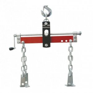
It does have holes all the way along it to tie into, but I was thinking just to bolt-clamp onto the 1/2" thick "tabs" that have the 3-point hardened balls set into them. The ties would go straight up onto one of those adjustable arms used with car engine hoists to get the suspend over the centre of gravity, though maybe with some alternative to the big chains, which might cause damage.

But - you are both right! The need to spin it over on it's axis to ink it is a prime requirement. Hmm..

[Edit: Maybe fix it to a plank at it's Bessel points, and give the plank jig end cheeks with a rotation bolt in each, and hook onto those? ]
[Edit2: Maybe even can do without the leveler]

Leveler.jpg
 
Last edited:
I think what C-Bag was asking was if the cast iron straight edge had bolt holes on the ends, so that the line along the long axis through the bolts passed through the straight edge center of gravity. That way if you lifted it from those bolts, you could rotate the flat face of the straight edge up to ink, then rotate again to print. Admittedly that is not hoisting by the Bessel points.
I’ve seen some Russian straight edges with those bolts and with cast in knobs for rotating on axis. That 48” long I beam casting is pretty stout. I wonder if there is any measurable sag if supported by the ends? I don’t see any way to easily rotate SE if supported by 3 or 4 points. Talk about moving the mountain to the mountain.
 
I’ve seen some Russian straight edges with those bolts and with cast in knobs for rotating on axis. That 48” long I beam casting is pretty stout. I wonder if there is any measurable sag if supported by the ends? I don’t see any way to easily rotate SE if supported by 3 or 4 points. Talk about moving the mountain to the mountain.
The edit on my previous post about using a plank with cheeks around it would, I think to allow the roll-over rotation, while only attaching at it's designed support feet.

It is very strong. You won't budge it when set on a bench, but it's self-weight is it's own enemy, Here we are not talking about just getting to hoist something heavy. We also want that it does not deflect even a tenth or two!

Unfortunately, without a big granite, I won't be able to measure the deflection if it were suspended by it's ends, but here, we might be able to compute our way to knowing that. The FreeCAD software on my computer seems able to do that. I only tried a simple cantilever beam tutorial example, but it seemed easy enough.
 
Last edited:
I think a support system with fixed-dimension components, whether they be cables or ropes, won't do what you want -- you need to move the straight edge back and forth to make a print. Fixed supports will require the supported object to rise and fall as it moves about, not conducive to making a good print. A counterbalance scheme to offset the major part of the weight in a Z-axis-insensitive-manner seems more appropriate to me. With a good enough counterbalancing setup you should be able to do things like the center of rotation test. So sez he, who has done nothing like this!
 
I think a support system with fixed-dimension components, whether they be cables or ropes, won't do what you want -- you need to move the straight edge back and forth to make a print. Fixed supports will require the supported object to rise and fall as it moves about, not conducive to making a good print. A counterbalance scheme to offset the major part of the weight in a Z-axis-insensitive-manner seems more appropriate to me. With a good enough counterbalancing setup you should be able to do things like the center of rotation test. So sez he, who has done nothing like this!
Hi Mark :)
Yes, in the way my.. ( revise that to "our" ) minds work, I have been playing out in my mind possible scenes of how the other experts might have have been doing it for decades. The whole deal swings on a support that is a radius away, which would lift it away if we move anything sideways. This time, we have the scheme to be able to move it to take the print, because of the 4:1 lever.

Start with the top support at the Unistrut. Once approximately overhead, we will not be expecting the rollers to move about any more, but it can if it has to. The cable goes to the lever piece of wood, 20% from one end, and a lump weight on the other end so we have a 4:1 counterweight, which balances the load down to something short of about a kilogram or so, the very last being taken in a little cord going to a cleat on the bench. This cord is by-passed by a slightly longer, fixed safety cord which sets the low limit - to prevent slip-ups. It allows the adjust cord to be (slowly) let go.

Taking a print movement can be by small movements which only cause rotation on the suspend cable. The end of the 4:1 lever would be relaxed enough so that there is some weight on the print, but perhaps not the whole load, when the cord is put into the cleat.

The final suspend is to the mid point of something like a 2x4 long enough to get to the ends of the axis gimbal. It sounds complicated, and I am going to have to attempt a sketch. I am tempted to leave out the final gimbal, and just tie on to the holes near the Bessel points. After a print, lift up a bit, and move it onto supports, like a weightlifter does. Then turn it over and ink as needed. I am likely to seek the simplest, least hassle way that still works. The practical value of trying some of this out is huge, but I am glad we have a plan that makes sense, and has anticipated dangers.

Me too - has done nothing like this! :) The contrast between one corner with a soldering iron and binocular PCB viewer, and over at the other end, a 40Kg lump of precision steel with a lathe bed, is striking!
 
Back
Top