What is this Clutch on my Gornati Leopard 180 ?

FredCailloux

Registered
Registered
Joined
Mar 5, 2023
Messages
14
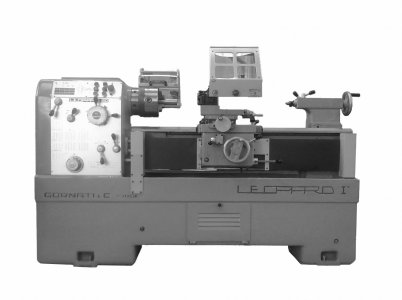
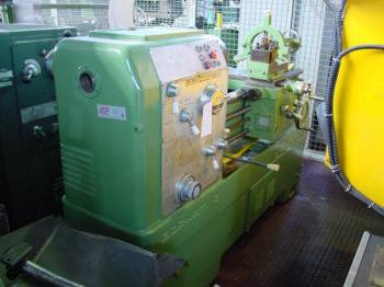
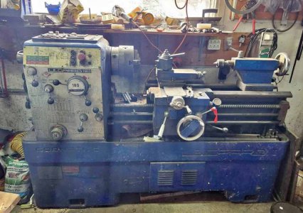
I'm in the process to completely refurbish my Gornati Leopard 180 Lathe. What a crazy idea!
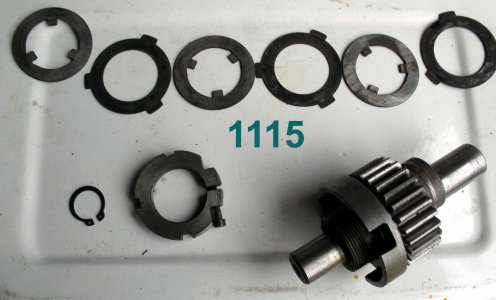
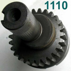
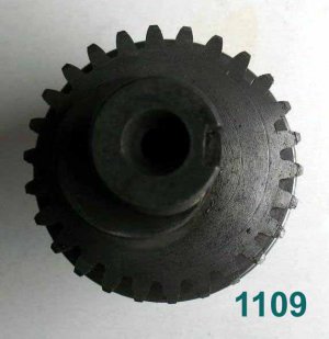
I found this clutch inside the Apron (not sure if that is the correct term, please bare with me, a newbie).
I'm trying to understand what's the purpose and how it works. I haven't seen any way to control it.
I suspect it is a safety clutch to limit the maximum movement force of the whole moving part.

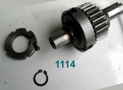
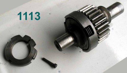
But the big question is : how do I take it apart?

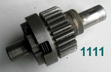
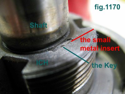
I was able to dismantle all clutch discs. Then I got stuck on image 1116. I've taken apart the lock washer and tried to gently hammer the shaft out but, no way!
This thing will not come apart. There is this rectangular lock insert made of two small metal parts (as shown with the red arrow). There is no way to take it out.
I'm afraid to bang the shaft further, I don't want to break anything.

Any idea anyone ?

More photos attached.


IMG_1112.JPGIMG_1116.JPG
 

Attachments

  • IMG_1115.JPG
    IMG_1115.JPG
    87.6 KB · Views: 12
  • IMG_1114.JPG
    IMG_1114.JPG
    84.9 KB · Views: 11
  • IMG_1113.JPG
    IMG_1113.JPG
    63.6 KB · Views: 12
  • IMG_1111.JPG
    IMG_1111.JPG
    59.3 KB · Views: 13
  • IMG_1110.JPG
    IMG_1110.JPG
    51.4 KB · Views: 12
  • IMG_1109.JPG
    IMG_1109.JPG
    44.7 KB · Views: 12
Don't know that it really needs to come apart any further if the shaft is in good shape. Most likely a press fit. and may only come out in one direction. Are the clutch discs good? How about a few pics of the lathe itself, and welcome to the forum. Mike
 
Welcome Fred,

Interesting problem. I need to understand more about what's going on there, in order to help.

IIUC, there must be rotational freedom between the two parts of the clutch (one part keyed to the ID of some discs, the other part keyed to OD of other discs). I'm assuming the outer cup of the clutch is integral to the spur gear. Is that assumption correct?

In the state of disassembly shown in image 1116 (clutch discs removed), does the outer cup/spur gear turn freely on the shaft?

It looks to me, in image 1116, that the threaded portion (w/ 3 slots to engage clutch discs ID) is integral to the exposed shaft. If they are not one piece, can you show/describe where/how they are connected?
 
IIUC, there must be rotational freedom between the two parts of the clutch. I'm assuming the outer cup of the clutch is integral to the spur gear.
In the state of disassembly shown in image 1116, does the outer cup/spur gear turn freely on the shaft?
Yes and No. Originally they were freely turning. Not anymore since I tried to dismantle the two parts with a hammer. I didn't bang too hard.
When I found that both parts didn't twist freely anymore, I immediately stopped insisting on taking them apart, so as to avoid any damage.
It looks to me, in image 1116, that the threaded portion is integral to the exposed shaft.
If they are not one piece, can you show/describe where/how they are connected?
Looking at the red arrow and the other red segment (1116).
They both point to the clutch inner 3 slots threaded holder ( let's call it ICH, inner clutch holder) .
And also point to the single slot inserted with two small metal inserts as to lock the ICH on the shaft.
But that part is supposed to come out of the shaft.
It appear to me that it is locked in by these two small rectangular metal pieces inserted in the ICH.
The red arrow point to those two pieces and slot.

The way I understood the mechanism is that the Gear drives the outer tab clutch discs and the ICH capture the rotational torque by pressure.
This pressure is adjusted with the tapped collar on figure 1115. That collar will screw on the ICH.
The more you screw the collar on the ICH the more you put pressure on the clutch discs.
When satisfied with the clutch overall slip torque you tight with an HEX key.
The lock washer ( fig 1115 to the left of the collar) is to make sure the ICH doesn't get out of the shaft.

So, essentially, figure 1116 show 3 parts together. 1 shaft, 1 gear that receive 3 clutch discs with outer tab and 1 ICH that receive the 3 clutch discs with inner tab. Over these 3 part I should mention also the two little almost hidden pieces of metal locking the ICH on the shaft.

So, the ICH is locked on the shaft and the Gear should rotate freely on the shaft, but the ICH is not integral to the shaft. It is clear that it can come out for I did move it with a hammer after removing the lock washer from figure 1115.

Hope this help your understanding. Much appreciation for your help.
pls excuse my poor English, I am a native french Canadian.
 
Here is an image of the Leopard 180 model from Gornati. This is not mine. It is an image obtained from the web.
Mine is much more dirty and grease. Hence the need to revamp it. The Leo180_Market.jpg is the actual model just acquired.
 

Attachments

  • Leopard_180_Small.jpg
    Leopard_180_Small.jpg
    161.6 KB · Views: 11
  • LeoPard_180_Petit.jpg
    LeoPard_180_Petit.jpg
    15.9 KB · Views: 11
  • Leo180_Market.jpg
    Leo180_Market.jpg
    97.4 KB · Views: 11
<snip
It looks to me, in image 1116, that the threaded portion (w/ 3 slots to engage clutch discs ID) is integral to the exposed shaft. If they are not one piece, can you show/describe where/how they are connected?

Just to be clear, the ICH is a separate part from (not integral to) the main shaft? Is that correct?
 
It's a fricion clutch, non-resettable and nonadjustable (beyond initial setup), so no problem burying it in the apron. You will need to rely on that part operating as it was meant to, so whatever is binding will need to be remedied.

I'm not sure what I am seeing in pic #1116. Is that supposed to be keyed? The keyway looks "packed" or even soldered, does not compute...
 
Just to be clear, the ICH is a separate part from (not integral to) the main shaft? Is that correct?
Yes, that is correct. There is a shaft that holds the ICH and the Gear. The Shaft has a Keyseat and the ICH as a Keyway. The Key is locked in place with some kind of a thin metal insert, it seams, fig.1170. This thin metal insert may have been added later to further secure the Key (my own assumption, for I have never seen this before)
 

Attachments

  • IMG_1170.jpg
    IMG_1170.jpg
    93 KB · Views: 9
  • Keyway-Illustration.jpg
    Keyway-Illustration.jpg
    95.8 KB · Views: 8
Last edited:
Back
Top