Ways to make a crank shaft

I agree with Bill in that I would be afraid to weld on the crank.
After you put all of the work into making the crank square and true, it would be a bummer to warp it out of alignment by the heat of welding.
You might get away with it, but I wouldn't go down that path.
Terry S.
 
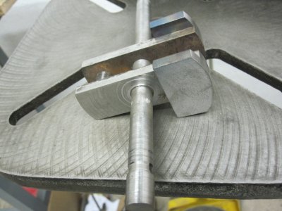
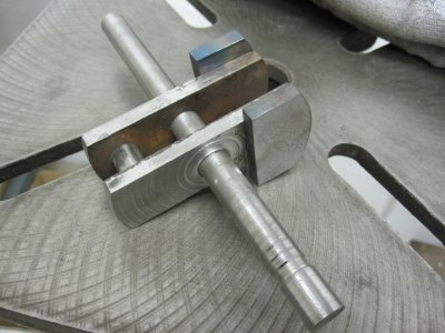
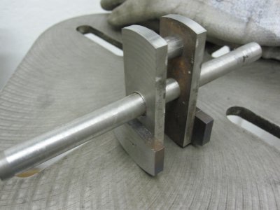
Been travelling a lot so I haven't had time to work on my personal project lately, until this weekend. Here is an update on my crank shaft for a steam engine. I guestimated the weights of the connecting rod and associated rotating parts and added a little to figure the needed counter weights for the crank. If too much, I can lighten the weights by removing metal. I did weld them in place, thought I would take a shot at it to see what would happen, then turned the whole thing down to clean it up. I still have not cut away the main shaft between the webs, but for now it is still nice and straight. Here are some photos of where it is now.

Crank update 007.jpgCrank update 005.jpgCrank update 006.jpg

Crank update 007.jpg Crank update 005.jpg Crank update 006.jpg
 
A question about the valve connecting rod: do I need to have a crosshead for that like I will for the piston? I will be using a piston style valve.
 
My opinion is that there is no need for a cross-head on the piston valve. Even large engines ran with the valve connecting rod coupled directly to the valve stem.

The reasoning is that the valve rod is determined by the cylinder connecting rod and is forced to be longer than needed. Furthermore, the offset of the eccentric is less than the crank offset = less angle applied at the valve / rod connection. Piston valves require much less driving force than slider valves. So the total side load on the valve stem at mid stroke is quite small.

Some notes on piston valve design:
1) The "piston" needs to be a tight sliding fit in the valve bore. Large engines used complex system of rings and ring cages on the valve pistons, but every model I have ever seen relies on a close fit without any seals. So you need to plan on drill / bore / ream the bore. Leave extra length (mabe 2") on the valve stem so you have something to chuck when you lap the piston / bore to final size. Then carefully remove the excess length on the valve.

2) Materials: the housing with its bore is the most difficult part to make. So the valve piston was always designed to be the wear part. The valve is quick and easy to remove for inspection, and it is not too difficult to fabricate and re-fit a new one if the valve ever becomes to "leaky." I recommend a brass. Pick an alloy that is readily available. Get enough material to make several valve pistons in case you want to experiment with timing the engine and the expansion. Likewise, use a harder material for the valve body - but one that is easy to get a good internal finish. I would look at one of the "free machining" steels such as 10L18. This part will require some drilling and tapping for mounts, steam & exhaust and cylinder connections.

3) Basic design: there were many designs for piston valves with "balanced" load. Some were very complicated. For a model engine, I think the best is the "2 notch" design. It only requires 2 reliefs to be turned into the piston. The position of the reliefs as well as their widths determines the engine timing and expansion ration, so it is an exercise in accuracy to turn in these reliefs. Likewise in the valve body there are a number of holes drilled to connect to the A and B side of the cylinder, and to the steam and exhaust ports. All of these holes must be precisely located to achieve smooth operation. Larger diameter valve bores allows for shorter valve strokes, but it appears that the optimal point occurs in the range of valve bore = 30% of cylinder bore. If you try to make the stroke too short, it is difficult to accurately machine the very narrow piston valve reliefs required. I think you want to design the valve piston first (so it is easy to machine) and let that design determine the valve stroke (which determines the eccentric offset).

Terry S.
 
If I run the engine with air, the piston and ring material is not so critcal. I was going to use UHMWPE rings and aluminum bodies with thick wall DOM steel tubing' with a polished bore, for the cylinders. However, if I decide to use steam, the UHMW may not withstand the temperature. So I have thought that I could use PTFE for the rings. If I run steam at 150 psi gauge pressure, the temperature should be approximately 350-365 degrees F, which is well below the PTFE temperature limit. Also, I think that aluminum may be attacked in steam and so I should probably use either brass or steel for the bodies instead. Does this make sense? I am open to other solutions.
 
Another question: Is there some sort of formula to determine what the size and weight of the flywheel should be?
 
Another question: Is there some sort of formula to determine what the size and weight of the flywheel should be?

The general rule for flywheels on steam engines is the biggest wheel you can fit into the system. So, I guess the question then is what would be the minimum size? A flywheel stores most of its kinetic energy in the outer diameter where the radius is the greatest and the speed is the highest (stored energy goes up as the square of the surface velocity). That is why most large engines you see have a flat outer rim with spokes going back to the hub. The outer rim of the flywheel was also sometimes used as a flat belt driving surface. For model engines, solid flywheels are probably a lot easier to make than spoked wheels - but spoked wheels look cool.

I looked though a couple of old textbooks from the early 1900's. They mostly say to find a similar engine that runs well at low rpm, then scale the flywheel according to engine horsepower - not sure what they meant by that. I did find one rule of thumb on flywheel diameter: a good starting point for a single cylinder, double acting engine is to set the flywheel OD at about 4X to 6X of the crank stroke. So for a 1" crank = 2" stroke: flywheel diameters of 8" to 12" gets you in the ball park. For the width, I guess I would start with something that looks stable - probably a width of about 10% to 20% of the diameter.

Terry S.
 
Thanks, Terry S.

I agree with you that spoked flywheels look cool. I don't have the capability to cast a flywheel, so I am trying to work out a way to machine one, maybe in several pieces to look like a cast wheel with curved spokes. If I make it in pieces, I will pin and weld everything together so it doesn't fly apart, and balance it so it runs smoothly. Thanks for the sizing "rule", that should work well and look proportionally good.

I think as I move forward with my build I will open a new thread rather than keep this one on the crank going. Thanks to everyone for all of the help in this new hobby. I am finding it to be very relaxing (and sometimes a little frustrating) and educational. Can never learn enough or stop learning, or your dead.

Thanks again.
 
Last edited:
Back
Top