- Joined
- May 7, 2023
- Messages
- 1,402
I’ve been here a while now, and have seen the subject of making pullies discussed both here and on the net a bunch of times.
The conventional thinking is to turn the bore and the sheave portions in one setup for the ultimate in concentricity, and you may agree with this and its ok if you do.
But there is a better way, let me explain.
When you turn out a pulley from stock, boring the center and cutting the v for the belt, it’s true that you make the most concentric part possible.
This part stays concentric right up until you tighten the set screw down on the key in the keyway. Once you do this the pulley is thrown off center by half of whatever clearance you left for it to slide over the motor shaft/drive shaft.
This may only be a couple thousandth or so and if in you’re use case this is acceptable, you can stop reading here.
For the pulley I need and in certain other similar cases you might want something better, if this interests you read on.
The pulley I’m making is for a nice little mini lathe I’m working on. This little lathe is accurate and mostly very nice right out of the box, but like anything else there were some corners cut either as a cost saving measure, a production requirement or worst case, both.
So what we have here is a Soviet bloc Bakelite motor pulley. Now the communists love their Bakelite. It’s cheap and easy to manufacture parts out of, and it has the added bonus of being dirt cheap when you stuff the mold with whatever random garbage you have laying around.
Here is an AK bayonet I bought due to being able to see the nylon string inside the molded surface.
![IMG_3681[1].JPG IMG_3681[1].JPG](https://www.hobby-machinist.com/data/attachments/423/423958-99ee475c017aced08b97566be4094aae.jpg)
This is a new 25yr old pully from my lathe that I'm replacing that is flaking away at the edges.
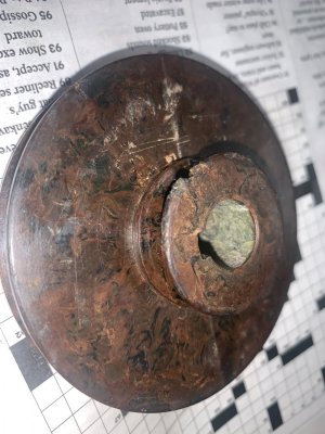
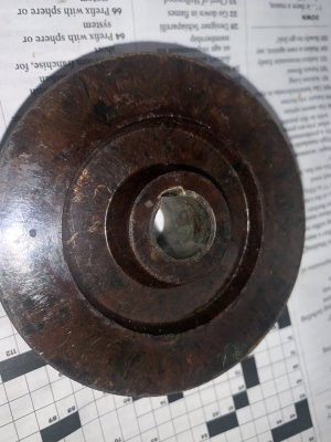
In the above pics you can see what looks like felt or old mattress ticking imbedded in the mix but I have seen nylon string, saw dust and wood chips etc.
This yields a part that not only is brittle, but also Has the benefit of being’s dimensionally unstable.
This means that if taken out of the mold too soon or if there is too much crap thrown in the part will deform over time.
For a clock radio or a knife handle this will not matter, but for a motor pulley on a high speed precision lathe it matters a lot. Considering the motor I'm using is turning 2500rpm, almost double what the factory motor turned, I'm not sure this pully will even hold up long term.
This pulley was so bad it shook the whole lathe enough that indicating a part under power was all but impossible, the indicator needle was just a blur before ever touching it to the part.
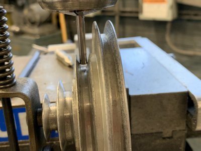
So I decided to make my own pulley that was not concentric with it’s self, but more importantly concentric with the motor shaft it’s running on.
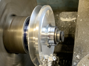
This will result is a pulley that runs much truer when mounted on the motor and is accomplished by doing the final turning on a mandrel.
Here I have already bored the hole for the motor shaft, broached it for the key and added a set screw that will engage the key seated in the motor shaft. Along side this is the piece of steel I will make the mandrel out of.
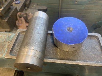
Now I’m turning down this large piece of steel rather than using something closer to the 15mm mounting hole/motor shaft, as I will machine in a register for the pulley to…., we’ll, register against to eliminate wobble and vibration during the cutting process.
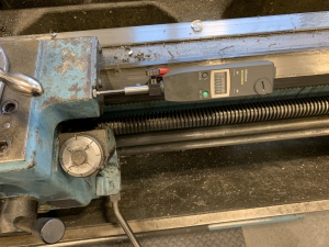
Here I’m checking clearance where my final depth of cut will be in regards to the tooling and the chuck and setting the carriage stop to this distance.
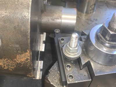
What I didn’t get a shot of is that I retracted the compound so there was no overhang and also centered the cutter tip over the compound's ways so there is little risk of deflection as I will be taking HEAVY cuts to hog out the material as fast as possible.
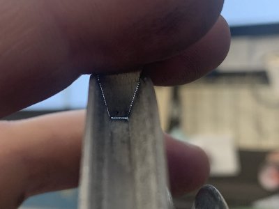
And for this you may have noticed I’m using a round carbide insert tool holder. These things are awesome for removing material fast and efficiently without creating a lot of heat.
Beauty shot. I think these inserts are ground and would be considered “aluminum” inserts, but they cut steel just fine and put up with all of my abuse.
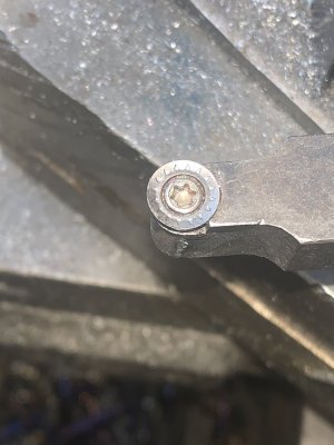
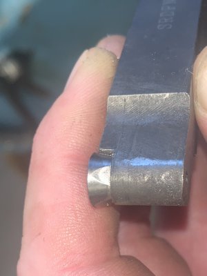
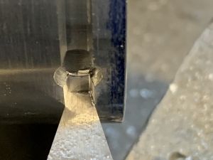
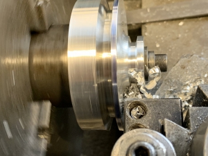
Here I’m just starting out by facing the part and you can see another advantage of the round insert, I can face and turn in one setup.
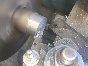
I love these inserts as it only took me 6-8 min to turn this 3” piece of barstock down to 15mm at 1.5” length. Wouldn’t even have taken that long but I had to creep up on the feed to figure the best feed setting as I was taking .200 D cuts. This really isn't even a heavy cut for this setup, but I will be using this same insert for turning the pully so I wanted to preserve the edge as much as possible.
You can see in the video I'm interrupting the cut every now and then also. And with cuts like that you can turn out nice lil purple catapillars that just drop right down into the chip tray.
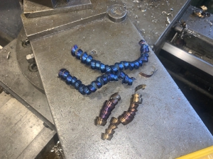
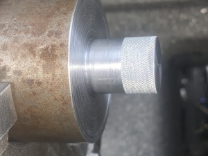
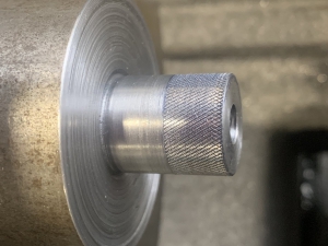
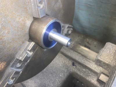
So when the smoke cleared I had my mandrel and it looked like this. The part with the bluing remaining and the shiny spot near the mandrel corner? Are undercut to ensure that only the mandrel body and the register come into contact with the part. You can also see the shaft has been drilled and tapped for a 5/16-18” cap screw.
Now, this is where the rubber hits the road as far as making this an accurate turning process given the fact that this is a keyed pulley.
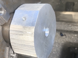
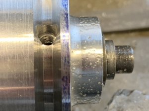
In the below pic you can see a piece of shim stock fitted into the key way. The sole purpose of this is to give the set screw tip something to push against and not mar the shaft which would leave a nasty burr on the precisely bored …..umm….. bore. This piece gets pushed into the keyway fully so the cap screw and washer can seat against the face of the part.
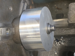
The set screw gets tightened down against the shim and then the 5/16” locking bolt gets tightened down.
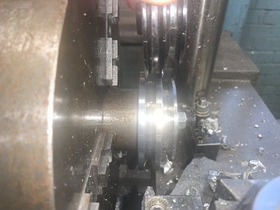
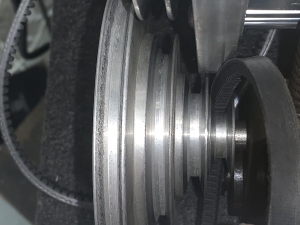
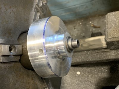
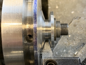
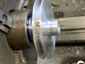
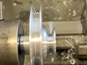
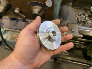
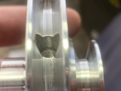
Now I have the part trapped both radially as it will sit on the motor shaft and also axially and I'm ready to go.
The conventional thinking is to turn the bore and the sheave portions in one setup for the ultimate in concentricity, and you may agree with this and its ok if you do.
But there is a better way, let me explain.
When you turn out a pulley from stock, boring the center and cutting the v for the belt, it’s true that you make the most concentric part possible.
This part stays concentric right up until you tighten the set screw down on the key in the keyway. Once you do this the pulley is thrown off center by half of whatever clearance you left for it to slide over the motor shaft/drive shaft.
This may only be a couple thousandth or so and if in you’re use case this is acceptable, you can stop reading here.
For the pulley I need and in certain other similar cases you might want something better, if this interests you read on.
The pulley I’m making is for a nice little mini lathe I’m working on. This little lathe is accurate and mostly very nice right out of the box, but like anything else there were some corners cut either as a cost saving measure, a production requirement or worst case, both.
So what we have here is a Soviet bloc Bakelite motor pulley. Now the communists love their Bakelite. It’s cheap and easy to manufacture parts out of, and it has the added bonus of being dirt cheap when you stuff the mold with whatever random garbage you have laying around.
Here is an AK bayonet I bought due to being able to see the nylon string inside the molded surface.
![IMG_3681[1].JPG IMG_3681[1].JPG](https://www.hobby-machinist.com/data/attachments/423/423958-99ee475c017aced08b97566be4094aae.jpg)
This is a new 25yr old pully from my lathe that I'm replacing that is flaking away at the edges.


In the above pics you can see what looks like felt or old mattress ticking imbedded in the mix but I have seen nylon string, saw dust and wood chips etc.
This yields a part that not only is brittle, but also Has the benefit of being’s dimensionally unstable.
This means that if taken out of the mold too soon or if there is too much crap thrown in the part will deform over time.
For a clock radio or a knife handle this will not matter, but for a motor pulley on a high speed precision lathe it matters a lot. Considering the motor I'm using is turning 2500rpm, almost double what the factory motor turned, I'm not sure this pully will even hold up long term.
This pulley was so bad it shook the whole lathe enough that indicating a part under power was all but impossible, the indicator needle was just a blur before ever touching it to the part.
So I decided to make my own pulley that was not concentric with it’s self, but more importantly concentric with the motor shaft it’s running on.
This will result is a pulley that runs much truer when mounted on the motor and is accomplished by doing the final turning on a mandrel.
Here I have already bored the hole for the motor shaft, broached it for the key and added a set screw that will engage the key seated in the motor shaft. Along side this is the piece of steel I will make the mandrel out of.

Now I’m turning down this large piece of steel rather than using something closer to the 15mm mounting hole/motor shaft, as I will machine in a register for the pulley to…., we’ll, register against to eliminate wobble and vibration during the cutting process.
Here I’m checking clearance where my final depth of cut will be in regards to the tooling and the chuck and setting the carriage stop to this distance.

What I didn’t get a shot of is that I retracted the compound so there was no overhang and also centered the cutter tip over the compound's ways so there is little risk of deflection as I will be taking HEAVY cuts to hog out the material as fast as possible.
And for this you may have noticed I’m using a round carbide insert tool holder. These things are awesome for removing material fast and efficiently without creating a lot of heat.
Beauty shot. I think these inserts are ground and would be considered “aluminum” inserts, but they cut steel just fine and put up with all of my abuse.


Here I’m just starting out by facing the part and you can see another advantage of the round insert, I can face and turn in one setup.

I love these inserts as it only took me 6-8 min to turn this 3” piece of barstock down to 15mm at 1.5” length. Wouldn’t even have taken that long but I had to creep up on the feed to figure the best feed setting as I was taking .200 D cuts. This really isn't even a heavy cut for this setup, but I will be using this same insert for turning the pully so I wanted to preserve the edge as much as possible.
You can see in the video I'm interrupting the cut every now and then also. And with cuts like that you can turn out nice lil purple catapillars that just drop right down into the chip tray.

So when the smoke cleared I had my mandrel and it looked like this. The part with the bluing remaining and the shiny spot near the mandrel corner? Are undercut to ensure that only the mandrel body and the register come into contact with the part. You can also see the shaft has been drilled and tapped for a 5/16-18” cap screw.

Now, this is where the rubber hits the road as far as making this an accurate turning process given the fact that this is a keyed pulley.
In the below pic you can see a piece of shim stock fitted into the key way. The sole purpose of this is to give the set screw tip something to push against and not mar the shaft which would leave a nasty burr on the precisely bored …..umm….. bore. This piece gets pushed into the keyway fully so the cap screw and washer can seat against the face of the part.

The set screw gets tightened down against the shim and then the 5/16” locking bolt gets tightened down.

Now I have the part trapped both radially as it will sit on the motor shaft and also axially and I'm ready to go.
Last edited:


![IMG_3677[1].JPG IMG_3677[1].JPG](https://www.hobby-machinist.com/data/attachments/423/423956-f322834bd49a5565238067f4c3424a51.jpg)
![IMG_3703[1].JPG IMG_3703[1].JPG](https://www.hobby-machinist.com/data/attachments/424/424075-4af68b2cb051e43ff074625f65974aff.jpg)
