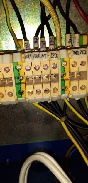
VFD wiring to mill control box

In the meantime, how do you change the direction from cw to ccw using the vfd?
 
It may seem confusing, but it's really not if you take it step by step. We can walk you thru it. Post or take a photo of the page of the VFD manual that deals with the external control connections and we can go from there
-Mark
Hi Mark.
Ok I cotacted Varispeed and the mailed me thr manual. I know you asked for the section external control, but I don't want to leave anything out so here is the complete manual.

 
Here it is
 

Attachments

  • alpha-drive-micro-manual.pdf
    37.3 MB · Views: 9
Hi guys
I just wished that there was a schematic of the wiring stuck to the machine, that would have made it much easier for me. Anyway.

I tried today to figure the wiring out, but I'm just not getting it, and my machine is almost up against the wall with very little moving space. I am giving you some pics and info but I don't think it will be enough. I will give it one more go tomorrow if tome allows.

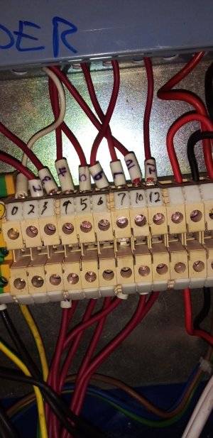
Right, pic below is where those red wires, with a numbers, come from the power supply somewhere.
20210520_133401.jpg
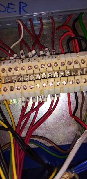
Then they go to the control panel.
20210520_133505.jpg
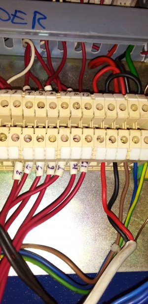
20210520_133605.jpg
Then they come back and are magically turned into four black wires also marked.
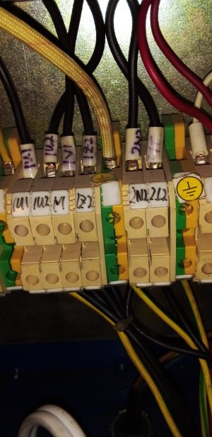
20210520_133930.jpg
Then those four wires went out to the old motor.
20210520_135746.jpg
I will see if I can make out wich of those red ones went where on control and wich positive and wich neutral. I will try and figure out the same with the black. Please be patient, because I don't know what I'm doing.
 
Can’t you use a continuity tester (multimeter) to trace the wires?
 
Don’t know what’s available by you but cheap ones are plentiful in general and will be very useful for this and any other electrical task. As a continuity tester, it will tell you if the two probes are electrically connected. Alternatively, you could use a battery, suitable light bulb or LED, and a couple pieces of wire.
 
Back
Top