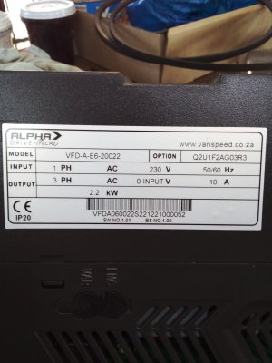
VFD wiring to mill control box

Suzuki4evr

Registered
Registered
Joined
Sep 29, 2017
Messages
2,253
Some of you may know about my single phase to three phase conversion on my mill thread, but I want to post this here seeing that it is a electrical question.

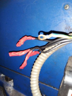
How do I wire the four black wires that comes from my controle box to my VFD so that I can use the CW,CCW, STOP AND EMERGENCY STOP on the controle box and not on the VFD?
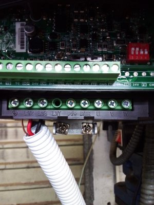
20210518_163053.jpg20210518_162952.jpg
Any advice would be welcome

Thanks in advance.
Michael
 
Can you provide a simple schematic of how the black wires are connected to the switches on the control panel?

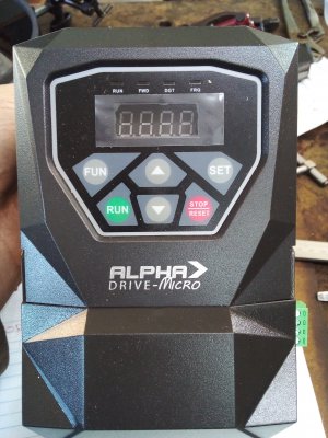
Also VFD model?
 
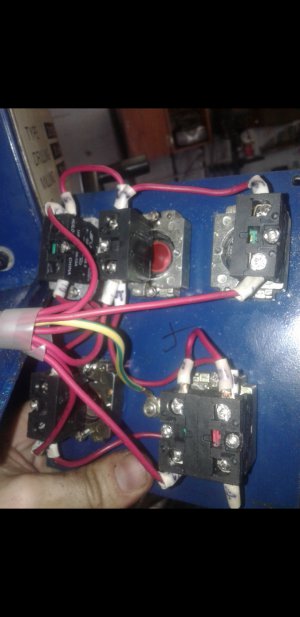
Let me put it like this, from what I can tell is that there is alot of red wires coming from the main electric box to the controle box with everything I mentioned.
Screenshot_20210518-194158.jpg
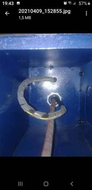
Then it goes back to the main box in a separate loom and comes back as four black wires plus the earth into the controle box, making a loop and then goes out again. And those four wires plus earth went to my previous single phase motor.
Screenshot_20210518-194309.jpg
20210517_113554.jpg20210517_113638.jpg
I hope this helps, it's the best I can explain it.
 
First thing to determine is what do the VFD inputs look like electrically speaking? Are they expecting contact closures to ground or to a plus voltage from the VFD? You need the documentation for that.
Secondly, are the switches in your panel the proper type? Momentary or non? How many poles?
Then you may have to rewire the control panel to give the proper switching arrangement that the VFD expects to see
Does that make sense?
-Mark
 
:confused::oops::rolleyes::xmaslights:

Does that make sense
I hope my emojis explain my answer.:laughing:
I think the best would be to get my brother inlaw (electrical engineer) here to help me. But for the time being, I will run it through the VFD panel, because I basically use the machine almost every day. But thanks for TRYING to help.

Michael
 
Michael,

Without knowing the exact wiring of your front panel, it is hard to give you a precise answer on how to connect it. Unfortunately the picture of 4 black wires plus the pictures of the bundle of red wires provide an incomplete picture of what that wiring looks like.

I'd be happy to help you set up this wiring if you can take the time to carefully sketch a schematic of exactly how this unit is wired.

Typically the VFD provides a voltage source for connecting the switches (eliminating the need for an extra power supply) so that helps us. Knowing the exact arrangement of the switch wiring will help determine what type of control circuit is needed (look up 2 wire vs 3 wire motor control circuits).

Otherwise there is nothing wrong with using the front panel connections until your brother-in-law can come see it in person.

Mike
 
Ok Mike, give me a little time so I can trace some wires and try to help you help me. Will see if I can have a look tommorow.

Michael
 
It may seem confusing, but it's really not if you take it step by step. We can walk you thru it. Post or take a photo of the page of the VFD manual that deals with the external control connections and we can go from there
-Mark
 
It may seem confusing, but it's really not if you take it step by step. We can walk you thru it. Post or take a photo of the page of the VFD manual that deals with the external control connections and we can go from there
-Mark
When my brother inlaw got the motor and vfd, he tested it too see if it is working, but I left the book with him because he kinda wanted to go through it and he is about 60km away from me. The distance isn't the problem, it is the time to go get it. I feel a bit silly now for asking fot help and are not prepared to do my part. Sorry guys. I think the best for me is to wait for him when he has got time to come and help me. Once again thanks for trying to help. I will keep you updated.
 
Back
Top