VFD setting for YL620-A 1.5kW air cooled

Have no idea what they are talking about, you are just scaling the voltage output, it is also different based on the VFD model. I would contact the dealer that sold it to you.

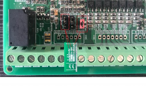
If it works with an external speed pot to the 10V VFD input then it may be a loading issue, maybe put a voltmeter on the COM (XGND) and AI1 with everything connected and make sure the voltage is changing. One reason why it gets pretty frustrating working with these generic VFDs, the manuals tend to be very poor and no technical support.
Yes I have tested that as you mentioned and all is working OK in that department.
Contacting the dealer is a bit of a joke, the dealer doesn't know anything at all about the product and was no help what so ever.
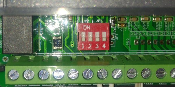
The manuals are confusing and not explained well at all, and in some cases lead one astray as with the JP1 that there is no reference for.
I guess it is up to us to help the next guy or gal that has a problem.
 
The reference voltage is being produced with a LM358 board that produces 0-10 volts from the 5V PWM signal. It is working fine producing 0-10 volts across the range.
Found out the settings needed.
P03.12 =30 (any lower the spindle will not start properly, higher will make the start RPM higher also)
P03.13 =400 (highest RPM for the spindle)
After setting, shut down the VFD and restart and it will work OK.
The range is working OK except the highest frequency is around 270 instead of 400.
Also the spindle is getting very hot while before it would run cool for hours.
I wish I had kept a record of the original settings so that I could go back and start again.
The original settings were not factory defaults I found out, so now another problem.
 
I was not following that you are running a high speed spindle motor, it would be helpful if you included the motor specs and a bit more complete information as to the application. The typical application seen in this forum is mills, lathes, etc. with standard 50/60Hz motors. You need to match the upper/lower frequency and motor parameters in the VFD settings as previously noted.

On a high speed spindle motor you would not run it at the low speed range (in V/F mode, something like 40-50% of the rated motor base speed). One issue with this VFD is it probably only runs in a straight V/Hz as opposed to sensorless vector and the low end speeds below about 50% of the base speed, it will run poorly. You also may not have the base speed of the motor set correctly which would explain the top speed not being achieved (it runs out of voltage above its base speed, or 100%). I assume the base speed is 400Hz so that would be 100%. See the attached file, the column with line input frequency of 400Hz, and probably follow those parameters if they are similar to your motor. Since you do not have an auto-tune, the VFD cannot determine some of the motor specific parameters that would make the motor run better.

I record the default VFD parameters and then make a few changes and then test the changes so you know the effect. Most of the VFD's I work with have a computer interface which makes it a bit quicker to test individual parameter changes.
 

Attachments

  • YL620-A Setup table.pdf
    282.1 KB · Views: 74
I was not following that you are running a high speed spindle motor, it would be helpful if you included the motor specs and a bit more complete information as to the application. The typical application seen in this forum is mills, lathes, etc. with standard 50/60Hz motors. You need to match the upper/lower frequency and motor parameters in the VFD settings as previously noted.

Thanks for that very interesting data sheet, I had just finished working out some of the values and then you provide them almost the same as some of mine, but the data sheet will now provide any missing ones, thanks for that.

High Speed Electro Spindle
3 phase Model EYS8043-24/1.5
IP 54 3.5 Kg
220V 400Hz 8.0A 1.5Kw 24000 RPM 0.7 COS
Air Cooled

The spindle is being used on a CNC mill, the software and firmware are Estlcam 11, and the control board is based on Arduino Nano, the stepper drivers are TB6600, the Y axis uses two steppers, X uses 1 and Z uses 1, all are Nema 24 and are geared down to increase the torque.
Main power supply is 24 volts DC
The mill is running 2005 ballscrews on X and Y and 1605 on the Z axis.
The machine has Hiwin linear rails and carriages.
The control box I will be replacing with a new one using a similar configuration, but with more shielding.

The VFD and motor are the same as in this advertisement on ebay https://www.ebay.com.au/itm/CNC-240...let/292583519890?_trksid=p2485497.m4902.l9144
 
Last edited:
I have found a section that I don't really understand and there does not seem to be enough information available in the manual.
Settings indicate that I should use P00.01 = 1 and P07.08 = 1 and JP1 requires 2-3 feet short circuit (what ever that means) and no indication where to find JP1.
I know I'm late to this game, but maybe this helps someone in the future..

I THINK there is a translation issue here. when they say:
"JP1 requires 2-3 feet short circuit " it makes no sense, but...

if you translate the instructions to mean:
"Close the circuit between LEG (not "foot") #2 and #3 on JP1" then it becomes a little more logical.

JP = "jumper" (maybe).. these are the "jumpers" on the circuit board just behind the green row of screw pin terminals... Mine was replaced by 4 DIP switches, but an old schematic I found shows they are "jumpers." I have tried every configuration of DIP switches on mine and nothing changes, so this may be of help to NO ONE...


See the "manual" i found, that shows the "JP1" as jumpers (and gives more info in quasi-better English) below. It looks liek the one already posted except it has a picture of the "JP1."
 

Attachments

  • YL620-A Setup table 190707.pdf
    580.1 KB · Views: 36
Translations between one language and another are full of problems, especially when dealing with languages as different as English and Chinese. A few years back, I took on a project of making a brass plaque as a thank you gift for some services a neighbor had done. I selected a Chinese proverb which fit the occasion and decided to translate it into Chinese as well. I found a translation app online and did the translation. As a check, I translated back to English and the results were laughable. I also ran the translation past a native Chinese colleague and we finally decided that there was no way to properly translate the English version of a Chinese proverb back into Chinese.. Fortunately, the plaque was intended for someone who spoke no Chinese so the result was OK but if a Chinese person ever saw the plaque they would certainly get a chuckle out of it.
(https://www.hobby-machinist.com/thr...in-your-shop-today.14637/page-115#post-298744 , post#3444)

I worked for a company making medical devices and we were CE marking our products. One of the requirements for CE marking was to provide manuals in multiple languages. I recall that we gave one particular manual to a native German who also had an excellent command of English and I was tasked with reviewing her translation. Most of the translation was OK but some of the more technical stuff was ridiculous and I had to sit down with the translator and explain in detail what the intent of the text was before we could finally have a coherent and correct manual. Our technical writer wasn't much help as she was fairly good at writing in English but didn't speak a word of German and had no means of verifying the accuracy of the content of the translation.

In these days of software translators, coupled with writers with little or no knowledge of the products they are creating the translations for, it is a wonder that they make any sense at all. Some of the larger importers like Grizzly do a better job as they maintain a larger support team both stateside and across the pond.
 
well, i guess I need to clarify; I did not actually "translate" the manual -- most of it is still gibberish to me... I speak NO Chinese, but I dabble in philosophy and electronics, so I was trying to "translate" what other "philosophical possibilities" the authors could mean by "2-3 feet." After I thought for a while about what part of the body could be part of an electrical circuit AND MAKE SENSE with the nature of the question, then "leg" seemed to fit both criteria - once I realized "foot" = "leg," that made the "2-3" circuit logical, too!
 
Last edited:
I have found a section that I don't really understand and there does not seem to be enough information available in the manual.
Settings indicate that I should use P00.01 = 1 and P07.08 = 1 and JP1 requires 2-3 feet short circuit (what ever that means) and no indication where to find JP1.
I have YL620A and I was wondering of this "2-3 feet", english is not my native, but it was really funny.
There is another manual in the internet i found. You can find it, I can't add url.
By default YL620A works with 0-5V. I discovered that it can be changed by dip switches marked as JP2 and JP3. You just need to swith the first of 4 dip switches to on. I checked it really works. I don't know if it has ability to control spindle rotations by current and is it possible to turn it on with that switches. I checked that with voltmeter. Before I switched it on rpm are increased only to 5 V. After that voltmeter shows 7..8V but rpm are not increased. Then I switched the second to on as it described in manual linked above. But nothing changed. Then I tried the first one and it works.
You can google that manual with YL620-A Setup table 190707.pdf
 

Attachments

  • photo_2020-03-15_19-03-16.jpg
    photo_2020-03-15_19-03-16.jpg
    139 KB · Views: 49
I asked seller on aliexpress and he send me this picture.
 

Attachments

  • H1c148eae67d040b29a89d7d0756e8b48o.jpg
    H1c148eae67d040b29a89d7d0756e8b48o.jpg
    893.5 KB · Views: 50
I've got the answer from the seller about my version with dip switches. He said that it is 0-10V and 0-20mA when all switches is turned of. To set 0-5V i just need to turn on the first switch.
But in fact it is vice-versa. When all switches is turned off it works from 0 to 5 V and when i turned 1 switch on it starts working from 0 to 10 V. I checked it with voltmeter.


The No. 1 switch controls 0 ~ 5V and 0 ~ 10V, and the No. 3 switch controls 0 ~ 20mA
 
Back
Top