vfd grrrr snag

nightowl499

Active User
Registered
Joined
Dec 29, 2012
Messages
239
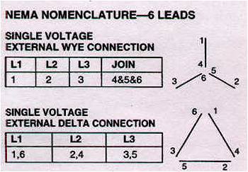
just starting to look at putting the vfd on my Harrison lathe now i see the motor has six wires...? 6 pole??

not sure how to wire the vfd three to the six on the motor. any thoughts ??
 
I will take a picture of it tomorrow and get info on it the specs on the plate on motor doesnt say anything about 2 speed but will look closer
 
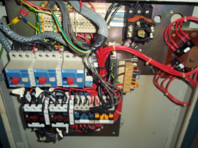
ok looks like the extra wires are figured out turns out they do pair up to just three on a terminal strip, so here is a pick of what im fighting with anything look familiar100_0570.JPG

100_0570.JPG
 
ok looks like the black thing in upper right is on off switch door the interlock. to right of that is the apron fw rv off switch, the blue row of box's are
breakers middle one marked spin the bottom row appears to be the contactors and next to the blue breakers is a transformer for the contactors

hmm its kinda sorta making sense
 
ok looks like the extra wires are figured out turns out they do pair up to just three on a terminal strip, so here is a pick of what im fighting with anything look familiarView attachment 84491

The following is my best educated guess as to the purpose of the components.

Starting at the lower left are the main motor FOR/REV contactors with overload relay above. (Red Bars)

Next is the coolant pump contactor with overload relay above. (blue bar)

Next is the control power (and E-Stop) relay (yellow bar)

To the right of that is the control power transformer.

On the far right are the FOR/REV switches.

The black thing top just to right of center is the main power disconnect switch.

Having said that, the VFD will replace the FOR/REV contactors, and be controlled by the FOR/REV switches.

The VFD will be wired directly to the motor, and looks like it could be powered up through the control power relay. It looks like the control power relay breaks all of the main power to the contactors, but I can't really tell for sure from the picture.

I hope this helps
 
Re: vfd contactor control

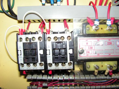
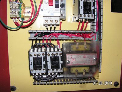
You can see in the pics that the contactors in the second picture are the original wiring that switches the motor on, off and direction. The first pic shows that the motor leads have been removed from the contactors and are now on the vfd motor output. The contactors now only switch the vfd control logic to command the drive to start, stop and reverse. This way the apron controls, e-stop, jog button and foot brake all function as original without rewiring them. The wires with red crimp on connectors are what I installed to control the drive commands.

PICT0729.JPG PICT0110.JPG
 
The following is my best educated guess as to the purpose of the components.

Starting at the lower left are the main motor FOR/REV contactors with overload relay above. (Red Bars)

Next is the coolant pump contactor with overload relay above. (blue bar)

Next is the control power (and E-Stop) relay (yellow bar)

To the right of that is the control power transformer.

On the far right are the FOR/REV switches.

The black thing top just to right of center is the main power disconnect switch.

Having said that, the VFD will replace the FOR/REV contactors, and be controlled by the FOR/REV switches.

The VFD will be wired directly to the motor, and looks like it could be powered up through the control power relay. It looks like the control power relay breaks all of the main power to the contactors, but I can't really tell for sure from the picture.

I hope this helps

Jim's decription of the Components is correct. As for the overloads, one is the main power, another is spindle overload, and the third is for the coolant pump. I wired the coolant pump contactor to pull in only when the spindle contactors runs.
I did however change my pump to 240v, single phase for simplicity.
 
Last edited:
Jim's decription of the Components is correct. As for the overloads, one is the main power, another is spindle overload, and the third is for the coolant pump. I wired the coolant pump contactor to pull in only when the spindle contactors runs.
I did however change my pump to 240v, single phase for simplicity.

Let me chime in and thank you for showing us your approach to the safety considerations with your solution. Moons ago I spent serious effort designing a circuit for my M300. My machine uses 120 VAC instead of 24 but is basically similar to yours in component configuration. Since I want to preserve the original wiring I think I will re-direct my efforts & use 2 isolating relays for FWD/REV & parallel them with the coils of the existing F/R contactors. This will let me isolate the low voltage F/R signals without overly disturbing the existing wiring.

AS ALWAYS---SAFETY FIRST

Thanks
 
Back
Top