VFD and Tachometer interference

Subw00er

Registered
Registered
Joined
Jul 5, 2020
Messages
22
I thought I'd be smart and get a 10v operable digital RPM gauge (chinese) and hook the display inside my vfd control box. It works pretty well, but it appears to be giving my VFD a hard time as I am seeing erratic readings on the display for the VFD - it wavering as if I'm playing with the speed POT (2-3% changes at random). When I unplug the magnetic sensor inside the lathe, the problem goes away. Will powering this off of its own power supply cure the issue, or do these two devices just not play well together in close proximity? My control vfd cable is well shielded, but the tach one was not (10v power ground and signal wires). Does that matter?

I'm thinking about adding a seperate 12v DC supply and changing the tach cable out to a grounded one, but I am not sure where to ground it as my VFD controller cable is grounded at the VFD but (as per the instructions) floating at the control box. So I don't really have a good grounding lug for the tachometer' shielded cable. I do think that it may be grounded by nature of being attached to the lathe via metal bracketry.
 
This is how I setup my cheap Chinese RPM readout for my lathe with a Hitachi VFD on it:
1) I used shielded control wire for the VFD controls. My lathe VFD controls are external to the VFD itself (I am not using the buttons and rheostat built into the VFD).
2) I used an EMI/RFI filter like this one on the single phase power input side of my VFD: https://www.ebay.com/itm/401264619208?epid=27007372697&hash=item5d6d3c2ec8:g:AC0AAOSwMWdddEOr
3) My digital tachometer is mounted inside the same control box as my VFD controls. I used shielded wire from the tach to the magnetic pickup.
4) I used a separate 12v power brick to power the tachometer. The 12v power supply is on the far side of the above EMI filter. So any EMI from the 12v power supply is isolated from the VFD by the EMI filter and visa-versa.

No problems so far!
 
All of Mike's suggestions are good. Sometimes one needs to experiment as far as where to connect the shield grounds, every situation is different.
You might find grounding one end or the other works better, or both ends. Or no ends, as Mark says below
Just shielding the tach might be enough, without adding a separate power supply. Hanging a 10 uF cap across the tach power might help too
-Mark
Check that the vfd low voltage output can supply enough current/voltage for the tach- the vfd manual should tell you
Keeping cable bundles separate is the single best, cheapest thing you can do and may be a total fix
Ferrite snap-on noise suppressors are sometimes useful
 
Last edited:
See if you move the tach sensor cable away from the VFD or route differently if the it changes the jitter. If it changes, this would suggest that the sensor cable is acting as an antenna. Route the sensor cable away from the motor cable, I have played with shielding on the sensor cable and in most cases I found grounding at either end or both made things worse, but results can vary significantly. May also try shielding ungrounded at both ends, this worked for me in the past.

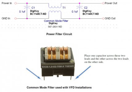
Use an isolated DC power supply, and/or you can try a common mode filter in the DC supply line to the tach.

Make sure you have the correct magnetic polarity, if incorrect polarity the signal will be weak and readings will be erratic.

Input filter on the VFD and//or motor cable can help, the latter probably less so because the noise is within the cabinet.

Make sure all you grounds are to one point (Star Grounding) or one buss.

Inexpensive tachometer often have poor noise rejection filtering both on the input/sensor side, you could always try a different tachometer.
Common Mode Filter.jpg
 
Thanks guys! I appreciate ideas. I'll try a few things as suggested.
 
I had similar problems when I attached a Chinese tachometer to my milling machine. It went crazy when I started the vfd.
The first thing I tried was putting two ferrite rings on the three outgoing cables from the vfd to the motor and that actually fixed the problem. Total success :)
 
I tried some Neodymium magnets near the wire to no avail, wasn't too hopeful on that as I didn't have actual rings. I ended up replacing the power supply and isolating the two circuits completely, and that seems to have done the trick. Maybe that helps someone in the future.
 
Ferrite rings are not magnets, totally different animal. In either case, good that you go it resolved.
 
Two wire tachometer pickups are quite noisy, and the voltage varies with speed. Three wire ones that take a dc power supply will be quieter, but they still male square waves.

Sent from my SM-G892A using Tapatalk
 
Back
Top