Vevor sewing machine motor as power source

fitterman1

What a view
H-M Supporter Gold Member
Joined
Jan 29, 2017
Messages
311
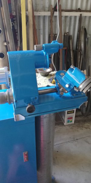
I'm using an industrial sewing machine motor for driving a dbit grinder which is nearly completely rebuilt.
The motor is vsd controlled, which made sense to me, being perfect for a sewing machine.
It came with a controller which is easily mounted under the worktable.
A power lead plugs into supply (240vac), another plugs into the controller for motor supply and a third is for the pedal speed function.
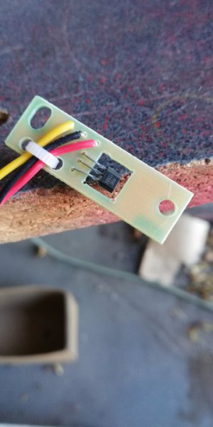
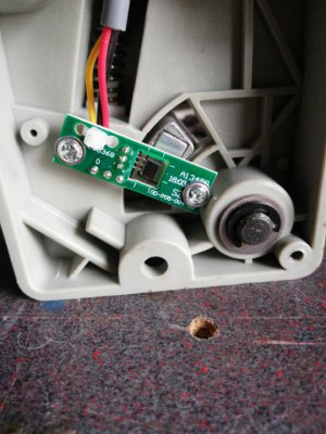
The pedal speed unit control looks like a transistor being influenced by a magnet which moves past as the pedal is pressed.
Is anyone familiar with this setup as i want to change this to an on/off switch, but don't understand what is going on with the small module and the magnet?
 

Attachments

  • IMG_20220506_105210.jpg
    IMG_20220506_105210.jpg
    47.4 KB · Views: 34
  • 16518013941263116265737866054425.jpg
    16518013941263116265737866054425.jpg
    79.8 KB · Views: 33
Last edited:
Yes, you're right but I can control the spindle speed, braking, and ramping in the parameters. This way I can specify optimal sfm for the grinding wheel.
 
I have one I’m about to put back on my mill/drill project. Definitely interested in how you control the speeds.

John
 
If it's a magnet moving past a "transistor", it isn't a transistor. It just about has to be a linear hall-effect sensor. It could look like a transistor -- it would have Ground, Vcc and Output pins. It just needs three terminals, that's why it would look like a transistor. If so, it wouldn't be all that difficult to replace with a potentiometer and (most likely) a little voltage divider network. The reason for the voltage divider network: the hall effect sensor's output range may only be a few tens to some hundreds of millivolts, while the Vcc input could be 3-5V (or more). Just trying a pot would likely produce a result that behaves like an on/off switch.

Getting the part number off the sensor and finding the data sheet will help speed you on your way. Otherwise you're looking at some additional experimentation to get it right. A couple of tandem-connected pots would help there: route the wiper pin of your lower-ohm pot to the top of your higher-ohm pot. The bottom pins would be connected together as "ground". The top pin of the low-ohm pot (say 1K) would go to Vcc. The wiper pin of the high-ohm pot (say 10K) would go to the Output connection. The top pin of the low-ohm pot would be connected to Vcc. Once you get everything set up, you adjust the high-ohm pot to set the motor speed. You'd start by adjusting the high-ohm pot so its wiper is connected to its top pin, then adjusting the low-ohm pot so the motor is running at your maximum-desired RPMS.

The reason I'm talking about low-ohm and high-ohm pots is that the pot connected to the other one's wiper will load it down, causing difficulties with regard to linearity.
 
I'll pull the small board out and get a number off the "hes" when I get home.
The motor powers the spindle quite easily for a 550W unit. Standstill to 4500rpm is instantaneous in response.
Parameters are easily adjusted within the menu, which I like and the motor is so quiet I have to look at the pulley to see if its running.
 
Last edited:
If it's a magnet moving past a "transistor", it isn't a transistor. It just about has to be a linear hall-effect sensor. It could look like a transistor -- it would have Ground, Vcc and Output pins. It just needs three terminals, that's why it would look like a transistor. If so, it wouldn't be all that difficult to replace with a potentiometer and (most likely) a little voltage divider network. The reason for the voltage divider network: the hall effect sensor's output range may only be a few tens to some hundreds of millivolts, while the Vcc input could be 3-5V (or more). Just trying a pot would likely produce a result that behaves like an on/off switch.

Getting the part number off the sensor and finding the data sheet will help speed you on your way. Otherwise you're looking at some additional experimentation to get it right. A couple of tandem-connected pots would help there: route the wiper pin of your lower-ohm pot to the top of your higher-ohm pot. The bottom pins would be connected together as "ground". The top pin of the low-ohm pot (say 1K) would go to Vcc. The wiper pin of the high-ohm pot (say 10K) would go to the Output connection. The top pin of the low-ohm pot would be connected to Vcc. Once you get everything set up, you adjust the high-ohm pot to set the motor speed. You'd start by adjusting the high-ohm pot so its wiper is connected to its top pin, then adjusting the low-ohm pot so the motor is running at your maximum-desired RPMS.

The reason I'm talking about low-ohm and high-ohm pots is that the pot connected to the other one's wiper will load it down, causing difficulties with regard to linearity.
What would be reading the hes?
Could it be possible to bypass this and have the main controller only?
 
Last edited:
Yes it is a "hes"
Here's the data sheet.
 

Attachments

  • IMG_20220506_143102.jpg
    IMG_20220506_143102.jpg
    40.5 KB · Views: 21
  • K1139513440.pdf
    500.8 KB · Views: 6
Last edited:
Tested without the hes plugged in brings up a fault on the display which means I have to bypass it somehow.
 
Last edited:
I have one I’m about to put back on my mill/drill project. Definitely interested in how you control the speeds.

John
John, I've picked this motor because it has the necessary torque to spin up a grinder spindle quickly. The only speed control required is for different sized wheels. This I can change in the parameters, if necessary.
I would go for a dc motor for what you want, a potentiometer speed controlled unit would provide excellent torque especially for milling. I use a treadmill motor on my G0602 lathe and it works great.
 
Back
Top