V42 spindle help needed

Wierd Harold

Active User
Registered
Joined
Dec 12, 2011
Messages
132
I am disassembling and cleaning the 10F babbit head lathe I just got and have a couple questions on the spindle assembly.
The previous owner mentioned he had the spindle out for some obscure reason as he also said he knew very little about lathes.
I am not sure if everything is back as it should be as I know there is a washer (9-89) missing.
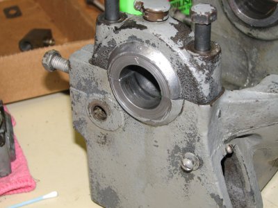
So , #1 does anyone know the thickness of this washer and is it located against the bearing in the picture (inside the head stock) or against the spacer (outside the head stock) ?
#2 is the bearing in the picture facing the right way ?
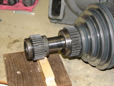
#3 how tight is the adjustment collar (9-39) on the end supposed to be ?
There seems to be a lot of wear on the end of the headstock on this end but not at the chuck end.
Any help would be appreciated .
Spindle.JPG

Headstock.JPG

Spindle.JPG Headstock.JPG
 
First, you'll need this View attachment Atlas 10 Parts list.pdf. Second, as you've likely already noticed, the bearings will only fit on one side of the headstock. That said, they will readily face either direction, as there is no registration mark or pin to make it fit one way. I would ask if you noticed any shims between the bearings, as that would allow a small bit of adjustment.

Also, I witnessed the majority of the headstocks I've come across, that the oil cup lids will face the operator. It isn't an absolute, but its a starting point. With regards to the spacer, it is outside of the headstock, followed by the 32tooth gear, and finally the locking nut.

You will want to your spindle to feel slightly snug when trying to turn it by hand, but not so much that you have to exert any effort to turn it. (That made no sense, did it?) You don't try to turn the bolts holding the bearings down as much as you can, adjust them a few times while spinning the spindle and you'll get an idea of what I mean. Same goes for the locking nut, don't try to make it super tight, its job is to limit forward and back movement in the spindle as well as keeping the 32 tooth gear in place.

Hope this information is useful.

Terry
 
Harold,

I don't know what the 9-89 washer thickness is but would guess about 1/8". If you cannot get one from Clausing, the OD and ID should be the same as that of the spacer. If you have to make one, start with 1/8", knowing that you might have to make a second one. I also don't know which way around the thrust bearing should be. If it will fit hard against the gear without the OD dragging, I would guess it goes the other way around from the way it is in your photo. If it drags at all, then it must go the way you have it.

The following is written assuming that you had to make the washer and aren't sure that the thickness is correct. Assemble the spindle and all components into the headstock. Snug the bearing cap bolts finger tight). Snug the 9-32 bearing collar finger tight so that the spindle has no end float. Attach the back gear subassembly to the headstock and engage back gear. Insert a .002" or .003" thick feeler gauge between the big end of the cone pulley and the bull gear and press the bull gear firmly against the gauge. Note how well the bull gear and small back gear teeth line up left to right. If they are within say 1/32", call it OK, tighten the bull gear set screw, remove the feeler gauge, and do the spindle bearing bolt tightening. If the gear tooth mesh was out more than 1/32", note the misalignment, make another washer with thickness calculated to bring the teeth mesh mismatch under 1/32" and try it again.

I have to disagree with previous comments on spindle bearing cap bolt treatment. They should be torqued to I would guess 20 to 25 lb-ft. Think automotive crankshaft main bear caps. Except that unlike that scenario, you have shims to play with. If your shim packs are missing, you will have to make some. Or see whether Clausing still has them. The thickness of the two shim packs under each bearing cap should be the same. With the bearing cap bolts torqued down, and the threaded collar loosened a little, the spindle should turn freely with no discernible drag and no discernible up-down or side-to-side movement. If it is too loose or too tight, remove or add shims. When removing another pair of shims switches from too loose to too tight, go back to too loose.

Finally, tighten the threaded collar for zero spindle end float with just discernible drag. Tighten the collar set screw and recheck.

Robert D.
 
With regards to torque values, I didn't see any in the Atlas manual. However, the manual does give some detail as to how they expected the bearings to be broken in and adjusted. I have included pictures of the relevant pages from the manual here, so you can make your own assessments.

DSCN0541[1].JPGDSCN0542[1].JPGDSCN0543[1].JPG

I'll also note, that I noticed while looking at the photo in the first picture in the upper left, that the oil cup lids are facing away from the operator. Yet the picture on the very next page shows them facing the operator. So much for consistency. If your lathe has seen much use, you may be able to use the wear marks on the bearings themselves to determine which way they were facing.

Terry

DSCN0541[1].JPG DSCN0542[1].JPG DSCN0543[1].JPG
 
And out of curiosity about that bearing, I just tore my headstock down, and removed the spindle. Mine has a metal spacer where the manual calls for the ball bearing to be. I'm wondering if that is due to my lathe being older, the serial number on the bed is D1345 which, if I'm not mistaken, puts it in the early 30's models. What year was yours produced, if you're aware?

Terry

I have another older Atlas that I believe is from about 1934 and is what I would call a "pre-D" 10-48 . My guess it is one of the first 10" models that still retained some of the 9" characteristics , such as the upper compound attaching with 2 "T" nuts and having a small knob for compound adjustment, also a 5/8" lead screw. This lathe is how you describe yours with a spacer in this position.

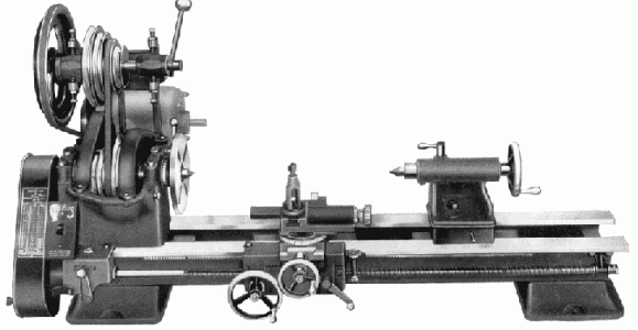
The newer lathe is a 10F (V42) and I don't know it's exact age. While researching today I came across an article about interchanging the spindles between a Babbitt bearing headstock and a Timkin
headstock and in passing they mentioned that the Babbitt model had a thrust bearing to take up the load when cutting toward the headstock while in the Timkin model the main bearings fulfilled this function .From the info here and what I have found on my own I have figured that the bearing in question is facing the correct way and just needs a washer to keep it from pushing directly against the Babbitt . Fastenal had washers in several thicknesses .

I also found while disassembling and cleaning the headstock that a previous owner had replaced the pin that is used to lock or unlock the bull gear with the pulleys with a short solid rod that was pinned in place through the hole where the spring and plunger should go so that you could not use back gears. I had to drill out the pin and make a new locking pin and plunger. A shortened pen spring worked just right .

Thanks for the help
HWF
 
The earliest dated catalog I currently have some sort of copy of is dated 1937. In it I find that the first 10" with a pintle mounted compound was S/N 3970. But there is no clue as to what year it was built. The only early 10" parts list I have come across is for the 10E, which has no lead screw (or change gears). These and things like countershaft, gear covers, etc., were separate accessories. The 10D was a 10E with all the options installed at the factory. The 10A and 10B lacked compound rest and back gears so were even more stripped down than 10E. So far, I've found no mention of a 10C.

The 9" was still for sale in 1937. My current best guess for the appearance of the 10A is 1935. The 10E has the ball bearing thrust bearing.

Robert D.
 
When I first got hold of mine, with the feet and such, this picture from the Atlas Lathes website is the spitting image of the one I have. And the website for those who've not seen it yet. http://www.lathes.co.uk/atlas/
img2.gif

The only thing I've never been able to locate is the door that goes on the end. According to the website this was produced in 1934, starting with what Atlas referred to as a Unit Plan system.

Terry

img2.gif
 
Terry,

I think that the sharp corner change gear guard was only produced through 1936. Same on the Craftsman 12" models. The Atlas and the Craftsman 1937 catalogs show the one-piece cover with rounded corners that remained in production for two decades.

I'm afraid that we've sorta hijacked Harold's thread. How are you getting on with reassembling your headstock?

Robert D.
 
Terry,

I'm afraid that we've sorta hijacked Harold's thread. How are you getting on with reassembling your headstock?

Robert D.

I don't mind. I read every post no matter what it is about or where it is.
The washers I ordered are coming today and everything is cleaned and ready to go.
The hold up on the project at the moment is picking paint.

I spent yesterday taking the carriage apart. The hardest part was getting the 2 big fillips head screws to break loose. They will definitely be changed to allen heads along with most of the others.

I also started making large dials for the cross and compound feeds.

As long as I am rambling on is there any actual difference in usability of the machine between horizontal and vertical drives ? I have both .

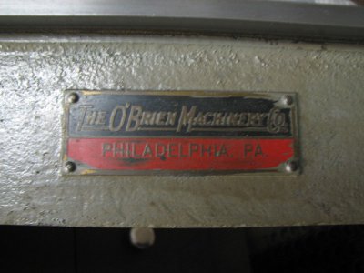
One more ramble. I found this plate on the back of the bed. I assume it was the original seller.

IMG_2537.JPG

HWF

IMG_2537.JPG
 
Back
Top