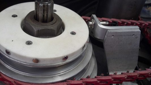
using hall proximity sensors with tachometer

Update and request for help. First I'll update with results of adding more magnets then I have another problem. Keep in mind I purchased the display unit that allowed changing the scale factor to select the number of magnets located on the circumference. I opted to go with 12 magnets and it read good at slow speeds, but as the speed got up to 500+rpm the last couple digits bounced around a lot. I changed out to only 4 magnets and I still read good at low speeds but had a much more stable readout at speeds 500+rpm without the last digit flickering. So I'll probable stay with 4 magnets. By the way, anyone who uses a unit like this with the hall proximity sensors needs to verify the polarity of each magnet before gluing them in place. The sensor will only pick up on one side of the magnet, if you flip it over, the unit won't read it.

Now the problem, the unit reads great up to 950-1050RPM then in that range it stops displaying speed until speed is dropped back down to 950rpm or less. It's not like you have a great deal of flexibility with these types of units so they should be fairly idiot proof, but I have now reached the end of my technical ability. So far I've tried the following things with no change in results;
1. Switched from 12vdc wall wart to my bench power supply to see if maybe unit wasn't getting enough current. Still won't read beyond ~1000rpm.
2. Cut down number of magnets from 12, to 4, then to 2 then to 1. (and YES I changed the prescale factor accordingly as I reduced the number of magnets) Still won't read beyond ~1000rpm.
3. I increased the distance from the magnets to the sensor to the maximum gap that it would still pick up at. Still won't read beyond ~1000rpm.
4. I decreased the distance from the magnets to the sensor to about 1mm. Still won't read beyond ~1000rpm.
5. I have two display units so I swapped them out just in case one was faulty. Still won't read beyond ~1000rpm.
6. I started out using 8mm dia x 3mm thick magnets, but also tried using 25mm dia. Still won't read beyond ~1000rpm.
7. I have an email message in the supplier of the display to see if they have any ideas. Not holding out much hope in this one since they're in China and more than likely just a reseller, plus a lot can get lost in translation. I only gave it a shot because on their page they said 'tell us your requirement, we can custom design for you.' So I was hoping they had someone with technical assistance.

Maybe someone with more technical expertise can think of something I'm missing.

You've got a 16 bit counter in there. There is nothing you can do about it. That's the limit.
 
UPDATE: I got a response back from the ebay seller in China less than 6 hrs after sending it off. They asked for pictures of the installation so they could have their engineer review. I sent pictures Saturday evening at 7pm, thieir response came back at 10pm. The engineers recommendation was for them to send me different sensors. Rather than use the magnetic hall sensors, they recommended a proximity sensor that would pick up iron vs magnet. So now I wait for replacements to see if they will work.

I'm horribly impatient and hate having to wait weeks to get the replacements, but I will say that I was impressed I got an answer at all let alone the response time from the seller 'TMALL'.

12 magnets.jpg
I don't know if the placement of the magnets is a problem or what. I placed my magnets on the perimeter versus adhering on the face of the pulley like 'mrpete' did in his video.

I even tried using just one magnet but the out of balance vibration at 500+RPM was too bad.

12 magnets.jpg
 
My additional 2 cents. My first attempt was a 110v trans down to 12vt dc. The skecthy instructions say 8-24 vts dc so I thought I was
safe, only lasted about 5 min and the display went brain dead. So I got another but using a 9vt common battery. The new one no directions
at all. The air gap I'm guessing now I find it to be around 10mm. So I placed the magnet turned the mill on and hand held the sensor and
it read 179-180 about what the mill chart says. Mr Pete says its a battery eater so I put a push button, no need for displaying all day.
Hate to drill a hole but I think one hole to hold the sensor and display box. Again I'll see it this one lasts.
 
- - - Updated - - -

Hi i bought 2 from the same seller as you for my lathe but mine are not adjustable and use one magnet. One works fine but the other one losses part of the last diget. Seller is sending me another display. I dont think i have tried it passed 800 rpm yet but i will now. I am using a 120v down to 12v adphter and no problems yet with lighting up.
 
Another Update:
The new inductive proximity sensors arrived from the seller and I gave them a try. They sense iron versus magnets. The results got worse. This time the display maxed out at around 350 rpm before it stopped picking up. So the "engineer" the ebay seller has seems to know about as much as I do about this problem.

As you could see from my previous picture with the original sensors I had been placing the magnets on the perimeter of the ring and only got to about 950-1000 RPM, I decided go back and try the original sensors and place the magnets on the top surface versus on the perimeter. With this change I actually hit about 1450 RPM now before it stops reading. Much improved but something still not right. I even tried increasing the magnet thickness to see if that would help pick up at higher speeds, no change.

Since the digital tach is really more of a novelty I've about reached my limit for dealing with this and scrap the whole idea.
 
What may well be happening is that, though the tach circuitry can handle inputs up to 5000 Hz, the sensors you are using may not be able to respond fast enough.

I've used quite a few Turck proximity sensors in previous years. Looked them up on the web just now, and (at least the models I looked at) are limited to ~2000 hz switching frequency. I'll offer a SWAG here and say that because proximity sensors need to sense a change in frequency response, they'll all have an inherent speed limitation.

I've not used Hall effect sensors.

My suggestion would be for you to consider using a photo sensor. Photo sensors generally have the simplest circuitry (an LED emitter and a transistor receiver), so they should be pretty fast.

Just for fun, I went to the Mach Tach's documentation page ... http://machtach.com/Docs.html looking for speed specs on their sensors. All I could find was the rise and fall times of their Hall sensor, which are 1.5 microseconds. This would be plenty fast enough for tens (or hundreds?) of thousands of RPM.

Another possible problem (mentioned in MachTach's documentation), would be interference from VFD wiring. I don't recall your mentioning if you have VFDs, but it seems you are able to easily vary the speed of your machines.

If nothing else, I'd suggest you go to MachTach's documentation page and download their User and Assembly manual. It contains a wealth of info.

PS - Not associated with MachTach, but I'm on their Yahoo group and have bought a kit (not yet assembled).

Best wishes!
 
Another Update:
The new inductive proximity sensors arrived from the seller and I gave them a try. They sense iron versus magnets. The results got worse. This time the display maxed out at around 350 rpm before it stopped picking up. So the "engineer" the ebay seller has seems to know about as much as I do about this problem.

As you could see from my previous picture with the original sensors I had been placing the magnets on the perimeter of the ring and only got to about 950-1000 RPM, I decided go back and try the original sensors and place the magnets on the top surface versus on the perimeter. With this change I actually hit about 1450 RPM now before it stops reading. Much improved but something still not right. I even tried increasing the magnet thickness to see if that would help pick up at higher speeds, no change.

Since the digital tach is really more of a novelty I've about reached my limit for dealing with this and scrap the whole idea.

Interesting, I almost think the sensor air gap could be critical. I set mine .032 with a brass gauge and works fine. sam
 
Interesting, I almost think the sensor air gap could be critical. I set mine .032 with a brass gauge and works fine. sam

So your able to measure faster speeds than 1400RPM? Are you just using the magnet they sent with the sensor?
I'm mounted around 1mm or so but I didn't measure like you did. I will try setting with feelers like you did and see if it get any better.

BTW; I had downloaded the Machtach manual (even though I didn't want to buy one of their tachs) to see if they had any info I could use about the sensors. I also did some searching for other info online about the switching frequency of sensors. The original hall effect sensors have a frequency of 320kHz and the new one they sent, the inductive sensor is only 0.5kHz. Somehow I did feel that the frequency was part of the problem. By my thinking, 320kHz is 320,000 pulses per second so It should be more than fast enough, right?
 
Back
Top