-
Welcome back Guest! Did you know you can mentor other members here at H-M? If not, please check out our Relaunch of Hobby Machinist Mentoring Program!
You are using an out of date browser. It may not display this or other websites correctly.
You should upgrade or use an alternative browser.
You should upgrade or use an alternative browser.
Tube Polisher....
- Thread starter JimDawson
- Start date
- Joined
- Nov 24, 2014
- Messages
- 3,175
One more detail.
I'm having a hard time anticipating the procedure for mounting/unmounting the pinion assemblies.
Recommendation: Make the bearing bore, in the 1" plate, a through hole (eliminate the shoulder in the 1" plate). Instead use a thin stainless plate, on the belt side, to retain the shaft/bearing/gear assembly. That way, the shaft/bearing/gear would pull out the belt side and the rear bearing support will slip radially free of the bull gear.
- Joined
- Nov 24, 2014
- Messages
- 3,175
Another idea. I'm not hard over about it but am throwing it out there FYI.
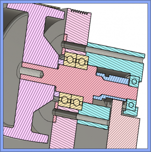
The idea is to make a steel flanged tube, that slip fits into (through) the 1" plate, from the belt side, and mounts the bearing pair. It is fastened in the same manor as (and instead of) the retainer plate I recommended above. The advantages are better thermal match to the bearings, more durable bearing housing (steel, not Al) and the bearing/shaft/pinion becomes a self contained cartridge so the bearings don't have to be pressed into/out of the aluminum plate. It looks like you'll have to increase the mounting fastener bolt circle a little to incorporate the idea.
The idea is to make a steel flanged tube, that slip fits into (through) the 1" plate, from the belt side, and mounts the bearing pair. It is fastened in the same manor as (and instead of) the retainer plate I recommended above. The advantages are better thermal match to the bearings, more durable bearing housing (steel, not Al) and the bearing/shaft/pinion becomes a self contained cartridge so the bearings don't have to be pressed into/out of the aluminum plate. It looks like you'll have to increase the mounting fastener bolt circle a little to incorporate the idea.
- Joined
- Feb 8, 2014
- Messages
- 11,144
Another idea. I'm not hard over about it but am throwing it out there FYI.
The idea is to make a steel flanged tube, that slip fits into (through) the 1" plate, from the belt side, and mounts the bearing pair. It is fastened in the same manor as (and instead of) the retainer plate I recommended above. The advantages are better thermal match to the bearings, more durable bearing housing (steel, not Al) and the bearing/shaft/pinion becomes a self contained cartridge so the bearings don't have to be pressed into/out of the aluminum plate. It looks like you'll have to increase the mounting fastener bolt circle a little to incorporate the idea.
I need to think on this a bit. I like the idea of the bearings removing from the belt side.
Last edited:
- Joined
- Feb 8, 2014
- Messages
- 11,144
Another idea. I'm not hard over about it but am throwing it out there FYI.
The idea is to make a steel flanged tube, that slip fits into (through) the 1" plate, from the belt side, and mounts the bearing pair. It is fastened in the same manor as (and instead of) the retainer plate I recommended above. The advantages are better thermal match to the bearings, more durable bearing housing (steel, not Al) and the bearing/shaft/pinion becomes a self contained cartridge so the bearings don't have to be pressed into/out of the aluminum plate. It looks like you'll have to increase the mounting fastener bolt circle a little to incorporate the idea.
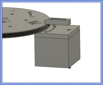
I finally got back to this, and added a SS retainer on the pulley side. Now as you suggested, the shaft will come out the pulley side. I may go ahead and make cartridge that will slide into the disk, I like that idea. I haven't had a lot of time to work on this.
- Joined
- Feb 8, 2014
- Messages
- 11,144
Getting ready to machine the main aluminum disk that rotates and supports all of the works. But...... It looks like I painted myself into a corner about a year ago and didn't even know it.
I made this 12'' diameter cast iron universal mounting plate for my rotary table for another project and it worked perfectly for that.
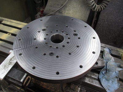
But I neglected to allow for any method of indexing the screw holes relative to my X/Y axis on my mill. Well this has come back to bite me. I can set rotary 0 anywhere, but in this case I need to align it with the work, thus align the screw holes with the work as well as be able to flip the work over and align it again. The obvious answer is to use some dowel pins installed into the cast iron plate. But how to locate them relative to the rotation of the rotary table and the existing bolt holes?
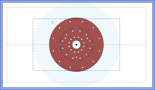
The blue circles show the location of the new dowel pin holes, but how to index them to the existing holes?
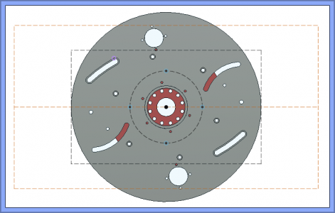
This is the way the work must sit on the plate. The inner dashed rectangle is the ideal work envelope for this project, and the outer dashed rectangle is the absolute max work envelope of the machine. I can easily reach all of the features inside the inner rectangle, then rotate 90 deg, and machine the other features. I also need to ''turn'' the OD and machine the belt grooves on the OD.
Once the dowel pin holes are installed, then it will be very easy to index them and 0 the table, but figuring out exactly where to drill them is the problem. I should have drilled locating holes when I first built the mounting plate.
I'm thinking use a couple of shoulder bolts in the outer screw hole circle, and use those to indicate off of.
I'll post some pictures of the setup when I get it figured out.
.
.
I made this 12'' diameter cast iron universal mounting plate for my rotary table for another project and it worked perfectly for that.

But I neglected to allow for any method of indexing the screw holes relative to my X/Y axis on my mill. Well this has come back to bite me.

The blue circles show the location of the new dowel pin holes, but how to index them to the existing holes?

This is the way the work must sit on the plate. The inner dashed rectangle is the ideal work envelope for this project, and the outer dashed rectangle is the absolute max work envelope of the machine. I can easily reach all of the features inside the inner rectangle, then rotate 90 deg, and machine the other features. I also need to ''turn'' the OD and machine the belt grooves on the OD.

Once the dowel pin holes are installed, then it will be very easy to index them and 0 the table, but figuring out exactly where to drill them is the problem. I should have drilled locating holes when I first built the mounting plate.
I'm thinking use a couple of shoulder bolts in the outer screw hole circle, and use those to indicate off of.
I'll post some pictures of the setup when I get it figured out.
.
.
- Joined
- Feb 8, 2014
- Messages
- 11,144
I drilled and reamed the dowel pin holes today.
Here is the process for locating them
First locate the center
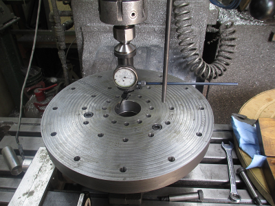
Then figure out where the holes are. I think I could have just located on one shoulder screw and been fine, but taking an average of two of them seemed like a better choice. The 12 inch scale is about the straightest thing in my shop, so I used that to indicate off of. It does have about 0.0015 bow in it over the length, but that's close enough.
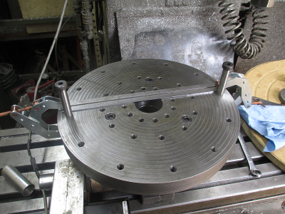
Now indicate the center
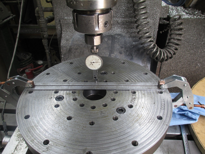
Then the left side
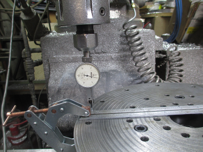
and the right side, and close enough. I'm not doing work for NASA.
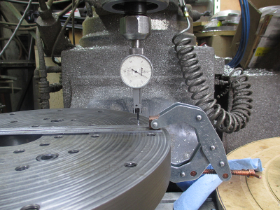
Then rotate 15 degrees to put the dowel pins halfway between the bolts, now it's in position for the first dowel pin hole
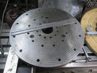
Then mount up the spoil board, I made this for another project so it bolted right on. I drilled and reamed through both the spoil board and mounting plate. I drilled through with a 1/4 drill, but only went 0.75 deep in the mounting plate with a 0.360 drill and a 0.376 reamer. With the 1/4 through hole, I can punch the pins out from the back side if needed, but they should be a tight slip fit in a 0.376 hole, so should come out easy with a pair of pliers.
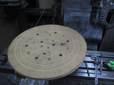
We had a 48x48x1 chunk of MIC6 plate on the shelf, but it looked like Swiss cheese, so had to find a location on it that I could get a 20'' circle out of without the holes impacting my finished piece. The first thing we did was locate all the holes and make a drawing of the locations.
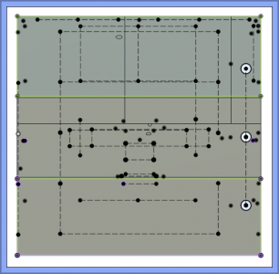
Then overlay the part and move it around until we could find a suitable location.
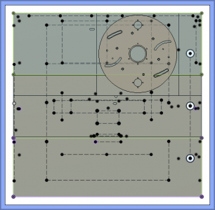
Then slice & dice to dig the raw stock out. And we come out with a 21 inch x 1 inch thick stop sign. We have an Evolution circular saw, 9 inch. I don't think they make these any longer. https://www.trick-tools.com/Evolution-Steel-Saw-5-TCT-Circular-Saw-with-Laser-Guide-SteelSaw5-6806 This saw does some serious cutting, cuts through aluminum plate like butter. We have cut 3 inch thick material with it.
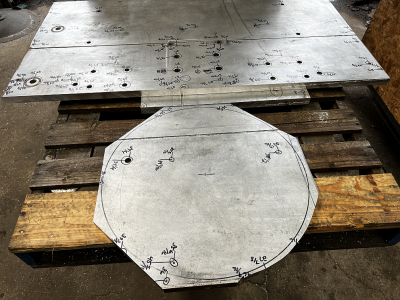
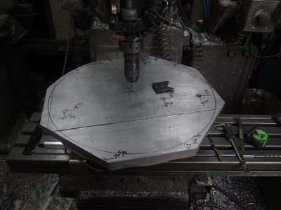
Then up into the mill with it, and center it up. Rotate so that hole on the right is in the proper location to not interfere with the machining.
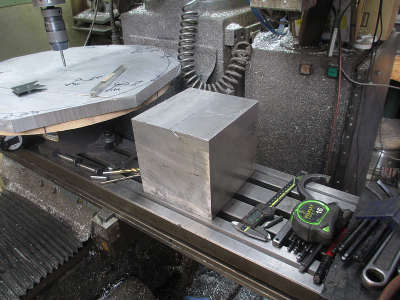
And that 6.5 inch aluminum cube is going to be a clamp for the work so I don't damage the rotary table when I start seriously machining on that chunk of aluminum. The rotary table gears just aren't designed for those kind of loads on a 20 inch circle.
That's my project for tomorrow
Here is the process for locating them
First locate the center

Then figure out where the holes are. I think I could have just located on one shoulder screw and been fine, but taking an average of two of them seemed like a better choice. The 12 inch scale is about the straightest thing in my shop, so I used that to indicate off of. It does have about 0.0015 bow in it over the length, but that's close enough.

Now indicate the center

Then the left side

and the right side, and close enough. I'm not doing work for NASA.

Then rotate 15 degrees to put the dowel pins halfway between the bolts, now it's in position for the first dowel pin hole

Then mount up the spoil board, I made this for another project so it bolted right on. I drilled and reamed through both the spoil board and mounting plate. I drilled through with a 1/4 drill, but only went 0.75 deep in the mounting plate with a 0.360 drill and a 0.376 reamer. With the 1/4 through hole, I can punch the pins out from the back side if needed, but they should be a tight slip fit in a 0.376 hole, so should come out easy with a pair of pliers.

We had a 48x48x1 chunk of MIC6 plate on the shelf, but it looked like Swiss cheese, so had to find a location on it that I could get a 20'' circle out of without the holes impacting my finished piece. The first thing we did was locate all the holes and make a drawing of the locations.

Then overlay the part and move it around until we could find a suitable location.

Then slice & dice to dig the raw stock out. And we come out with a 21 inch x 1 inch thick stop sign. We have an Evolution circular saw, 9 inch. I don't think they make these any longer. https://www.trick-tools.com/Evolution-Steel-Saw-5-TCT-Circular-Saw-with-Laser-Guide-SteelSaw5-6806 This saw does some serious cutting, cuts through aluminum plate like butter. We have cut 3 inch thick material with it.

Then up into the mill with it, and center it up. Rotate so that hole on the right is in the proper location to not interfere with the machining.

And that 6.5 inch aluminum cube is going to be a clamp for the work so I don't damage the rotary table when I start seriously machining on that chunk of aluminum. The rotary table gears just aren't designed for those kind of loads on a 20 inch circle.

That's my project for tomorrow

- Joined
- Dec 9, 2021
- Messages
- 735
I'm late to the party, but I wonder why you didn't use a centerless grinder as a basic design? It would seem you are doing something similar, and those are often designed for work to flow through continuously.
- Joined
- Jan 20, 2015
- Messages
- 359
Its bad form to retain two regular deep groove ball bearings like this. If both inner and out races are trapped you run the risk(pretty high) of forming a preload and damaging the bearings prematurely. They make double row ball bearings or you could use angular contacts but both are pretty expensive and unnecessary for an application such as thisI finally got back to this, and added a SS retainer on the pulley side. Now as you suggested, the shaft will come out the pulley side. I may go ahead and make cartridge that will slide into the disk, I like that idea. I haven't had a lot of time to work on this.
View attachment 409040


