Trouble reversing old GE motor, please help - confused!

rogersud

Registered
Registered
Joined
Mar 9, 2013
Messages
12
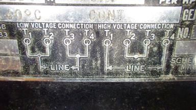
I have an old GE 3/4 HP motor model 5KC73AB206A. It's labeled "A-C Motor Dual Voltage Capacitor Induction". It is rated at 10A at 120V and 5A at 240V. It has 4 wires, one bump and bears a wiring diagrams as follows:

Low Voltage
T1 and T2 connected to L1
T3 and T4 connected to L2

High Voltage
T1 wired to L1
T2 and T3 only wired together
T4 wired to L2

I measure low DC resistance (<2 Ohms)continuity between T1 and T3. The same resistance is measured between T2 and T4. I'm assuming these to be the two windings.
I can measure no continuity between any even to odd wires combinations.

Based on these two facts, I assume that it is a split phase motor - one winding between T1 and T3, and another winding between T2 and T4.

When I wire it with the low voltage diagram with AC 120V, it starts and runs fine.
When I remove the voltage, it seems to continue to run for a second before a noticeable abrupt change in RPM.

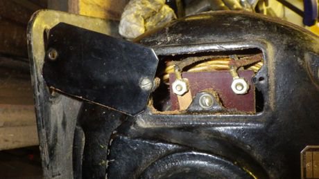
It also has an unlabeled removable cover with only two terminals underneath.

Here's the confusing part for me: If I try to reverse the rotation by reversing the phase of one of the windings like either of these:

Low Voltage
T1 and T4 connected to L1
T3 and T2 connected to L2

or

Low Voltage
T3 and T2 connected to L1
T1 and T4 connected to L2

... it pops a 20A circuit breaker immediately, with the shaft never even budging.

Is there something wrong with my motor?
Am I doing something wrong?
Is this a type pf motor that just cannot be reversed?

I would really appreciate any advice!

Thanks,

Roger
 
Hi ...

Bit busy at work and no time to read the finer detail here yet.

To reverse a single-phase motor you need to reverse the start-winding.

You are most likely paralleling the two windings up on lo-volts and running them in series in hi-volts.

The start winding is the one that will be switched out of circuit when running rpm is reached, usually via a centrifugal cutout. This winding, in relation to the other, you need to reverse.

Greg
 
You should have two start winding leads marked T5 and T8,

Can you post some pics of the terminal board in the back of the motor?
 
most single phase motors that are reversable note this on the wireing plate. does it list the rotation direction on the plate? not all single phase motors are reversible--- unless they give instructions on changing the rotation. Dave
 
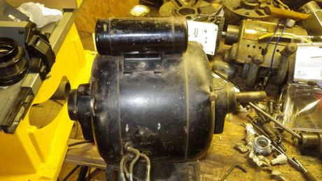
Thanks for the replies, all. Here are a few photos of the the important parts. The motor doesn't have a terminal board, just those 4 wires hanging out the side (the box that was around them has been removed to be straightened). They each have metal bands stamped T1, T2, T3 and T4.

The two terminals in the first pic are behind a plate on the non-shaft end of the motor. I was hoping to control this motor with a drum switch, but if I need to reverse the wires behind the plate, can the drum switch be used?

No, it is not specifically labeled as reversible.

inside.jpgMotor.jpgwiring.jpg

Thanks again!

Roger

inside.jpg Motor.jpg wiring.jpg
 
I agree with Dave Smith above. To be both dual voltage, and dual direction (i.e. reversible), you need access to three separate windings, meaning at least 6 wires.
http://www.naemotors.com/wp-content/uploads/2011/08/Single-Phase1.pdf


Thanks to all for the help with this. You definitely pointed me in the right direction. The two wires under the end plate were the key. Once I swapped those wires, the motor reversed direction. It will take some creative wiring, but I now know that I can safely set this up with a drum switch for 110V operation, but 220V operation on the drum switch would be totally unsafe.

Once I wire it and test it, I will post my wiring diagram for anyone else who might run into one of these motors.

Might try a double pole, double throw switch to reverse the polarity. Might find a double throw with a center off switch. Good luck.
 
I'd say you don't need 220 V on that small of a motor any how.

Thanks to all for the help with this. You definitely pointed me in the right direction. The two wires under the end plate were the key. Once I swapped those wires, the motor reversed direction. It will take some creative wiring, but I now know that I can safely set this up with a drum switch for 110V operation, but 220V operation on the drum switch would be totally unsafe.

Once I wire it and test it, I will post my wiring diagram for anyone else who might run into one of these motors.
 
Might try a double pole, double throw switch to reverse the polarity. Might find a double throw with a center off switch. Good luck.

The drum switch acts as the DPDT with center off. It also has an on-off-on SPST connected to the same handle, so that controls the hot lead, neutral is always connected, and the DPDT section handles the phase reversal. I'll have two separate conduits between the switch and the motor: four wires connected to end plate and two wires connected to the side. It will look a bit odd, but should work just fine.

I would have preferred 240V to lower the amperage, but it's true that 120V is not necessary for 3/4 HP.

Here is a PDF drawing of the circuit I plan to use.

View attachment MotorCircuit.pdf
 
Back
Top