- Joined
- Jan 1, 2014
- Messages
- 233
Transposing gears have to be either made or purchased. Since I don't have a dividing head, nor a turntable with an indexing capability, making them, I thought, was out of the question, and, unfortunately, buying these items to do the job of making them was too costly for something I do not regularly use.
I think I've read everything that members have posted on the subject and decided to try and make the gears with the resources at hand (10" SB lathe and a King PDM 30 bench mill with DRO ), but in a totally unconventional manner.
I needed to decide on a material to use first. Much is written on making gears out of plastic with Delrin the material of choice. Around here it is $65 a square foot (1/2" thick) which is expensive for what was going to essentially be an experiment. Opted to use HDPE at $11.50 a square foot, so an off cut 18" x 18" cost me $30.
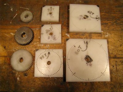
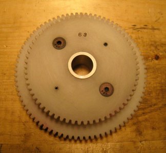
My plan was to use a jig to hold gear blanks in the vertical on my mill, and a toolbit ground to the necessary tooth profile in a fly cutter to cut the teeth. My lathe uses 16 DP, 14 1/2 PA gears, so I cut slightly oversize square blanks for 26/28/32/36/44/48/63/80 tooth gears. I had decided on a 63/80 transposing set for a little more accuracy. I also had access to a 26 tooth gear, and my lathe has 40/56/80 gears on it, so used the 26/40/56 gears to profile the tool bits to cover the ranges of real #2, #3 and #4 gear cutters. Grinding the tool bits took a lot of patience but looked pretty good when finished.
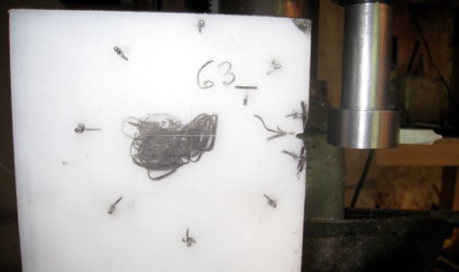
Accurate locating pins on the jigs to hold the blanks was also required. A .082" drill seemed to fit the bottom of the teeth on my gears so a little math determined the exact diameter of a bolt circle to use for each gear blank. These holes would eventually form the bottom of the tooth profile as well as serving to hold the blanks on the jigs for machining. The mill DRO bolt circle function is the only way one could do this, and, was dialed to the exact position on each hole, not .001" off but as exact as the DRO reads. This took some time but in the end each blank had an accurate hole circle as well as a centre hole.
The jigs were made out of the same HDPE material and were similarly made, but stragically drilled for just 7 or 9 locating pin holes. The locating pins were made from 1 3/4" finishing nails which coincidentally use .082" wire. Jig size accomodated a tail to be gripped in the mill vise.
The blanks were turned to size in the lathe, bored to size, and the keyway broached in using a simple 3/16" toolbit held in the tool post.
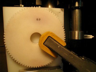
I used a backing plate behind each HDPE jig in the mill vise for support and mounted the blanks on the locating pins. The small ones were held in place by a cap screw and washer and the larger ones by a simple soft jaw carpenters clamp (the pins do all the work). This was the first test of how accurate the DRO hole circles and the locating pin layouts were. All of the gears fit the jigs without exception with a light press fit. I could flip or rotate them in any position with the same result, so was confident the milling process would be accurate as well.
Getting the flycutter on centre of the first hole required eyeballing and a magnifying glass to start with, taking a cut to half depth, then flipping the blank over, putting dye on the cut and running the cutter through again and adjusting the cutter height as necessary. I did this until flipping the blank didn't change anything - it had to be on centre! Depth of cut is supposed to be .134", so ran in to .125", and cut a number of teeth. Not having a Gear Tooth Vernier, I simply used my caliper to measure tooth width at the depth the jaws on the vernier sat, and compared them to one of the existing gears. Once satisfied the tooth was the right width, one pass was all that was required to cut each tooth. The blank had to be pried off the jig and indexed for each tooth, but was probably quicker than counting turns on an indexing head. Because the fly cutter never cut down to the bottom radius of the drilled hole circle, the finished gear had the same press fit on the pins as at the start, but a little easier as the top of each hole was now cut away. Most importantly, no mounting accuracy is compromised as teeth are progressively cut.
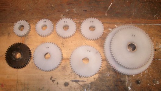
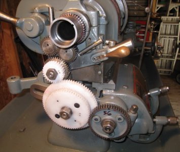
In the end, I have a full set of gears and the all important 63/80 transposing set to cut any metric pitch necessary. I won't brag and say they are 100% as good as conventionally machined gears, but they work, and the ratios are absolutely accurate. They will meet all my hobby needs for a fraction of the cost ($30). A downloaded transposing gear chart gave me all the necessary spindle gear and QCGB settings required.
I wasn't sure that this method would work when I started. but am very satisfied with the result.
I think the pictures are self explanatory but I welcome any questions.


Last edited:

