Torsional Beam Design Question

StudioMachinist

Registered
Registered
Joined
Oct 2, 2020
Messages
88
Almost finished with my lathe stand and want some ideas for the torsional beam. To be completely clear, I realize this is on the side of being unnecessarily over-built.

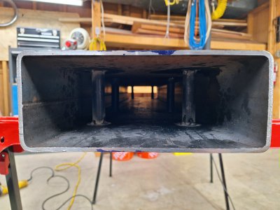
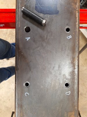
I've got a 3/16 4x10x60" square tube drilled out with penetrators for mounting hardware welded in place. The finished beam will be filled with non-shrink grout.

How would you do this?

Originally I was planning on welding plate to seal up the ends of the tube and then cutting out a window on the underside to pour the grout and then weld shut afterward.

Now I'm thinking, weld the headstock side of the tube only closed and just pour the grout tailstock side up. This is how Taig does their lathe, its simpler, and it would leave a full 7" of grout between the tailstock penetrators and end of square tube.

What do you think?1000000989.jpg1000000995.jpg1000001001.jpg
 
It seems that would give you the best fill. Mike
 
It's not over built. Looks good, so far.

Welding the ends shut will make a big difference if torsional resistance is what you're after.

Some diagonal members would also help. Looking from the top, something like XX. There's equations for this type of stiffeners because this type of weldment is fairly common.

I'm not so sure about the grout. Seems like it's effect depends on contact with the surface of the steel. If it shrinks a few thousandths, it's just a rock inside a steel case, effecting only the bottom of the beam because of gravity. With the passages for bolts, the rock may be suspended and have no effect at all. In any case, grout adds complexity to an otherwise straightforward design. Normal design of welded structures does not include any grout, for machine bases or otherwise. Almost everything you've ever read (on the internet) about damping in steel vs cast iron is over simplified and wrong for many situations.

How are you going to interface the lathe's feet to the beam? Scraping and Moglice are two options. I'm leaning toward the epoxy method, with jacking screws to adjust the bearing before injecting the Moglice.
 
Some diagonal members would also help. Looking from the top, something like XX. There's equations for this type of stiffeners because this type of weldment is fairly common.
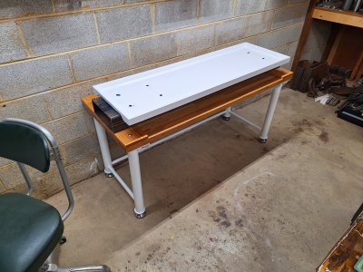
I think you are referring to the table itself here. Additional diagonal bracing was always the plan until I tested it and found how rigid it was. Couldn't seem to twist/bend it so in moved on with the build (will be easy to go back after and add to it if needed). Hard to see in the pictures but the way the legs are attached to the top is very stout.

I'm not so sure about the grout. Seems like it's effect depends on contact with the surface of the steel. If it shrinks a few thousandths, it's just a rock inside a steel case, effecting only the bottom of the beam because of gravity. With the passages for bolts, the rock may be suspended and have no effect at all. In any case, grout adds complexity to an otherwise straightforward design. Normal design of welded structures does not include any grout, for machine bases or otherwise. Almost everything you've ever read (on the internet) about damping in steel vs cast iron is over simplified and wrong for many situations.
Yeah this is a tricky one. I've also thought of using an anchoring cement that expands but that could just end up warping the tube and busting welds. There's also that engine jacket filling grout for race car motors, not sure how expensive that stuff is though.

As far as the connection between the lathe feet and the beam? I have no idea yet. Just thrilled all my holes lined up!
 
Just a comment, hope it's relevant. Not my statement, but seems to be true. This is my paraphrase, "Everything is made of rubber if you look closely enough". In my case, I was examining jaw lift of vises.

I'm not arguing for extreme overkill, but it was surprising to instrument the deflection and or movement, because it was far more than I had imagined. So do keep in mind that larger structures like a lathe stand may seem bomb proof, but aren't as rigid as first appears. All that aside, respectable work has been done on less than ideal lathe stands.

I'm due to make my own stand, primarily for mitigating storage issues. It doesn't appear that my stand is impeding me from making parts that match my skill set. Interested in your progress and will be following along.
 
Unless your parts have 5 Decimal places in tolerance, any you are trying to make that, this is already plenty good.

Weld it up and put it to use.

If you want to add mass for dampening, fill it with sand, pack it until no more can be added then weld it up.

Sent from my SM-G781V using Tapatalk
 
Unless your parts have 5 Decimal places in tolerance, any you are trying to make that, this is already plenty good.

Weld it up and put it to use.

If you want to add mass for dampening, fill it with sand, pack it until no more can be added then weld it up.

Sent from my SM-G781V using Tapatalk
Agreed. If not going for micron tolerances, it seems sturdy. If the OP does require that eventually, I'd hazard a guess that he could learn a great deal from this stand experience and will become more knowledgeable for a future attempt. Nothing like the wisdom of experience.
 
I am a little confused about this. How are you going to level the lathe? Shims? Why do you feel you need this "torsion bar"? In most situations the floor of the shop is the "torsion bar" and adjustable feet are spacers that get the lathe bed true.

To elaborate; your torsion bar is not ground flat or square. It will definitely warp the lathe bed when you bolt it down. Assuming it is rigid, there will be no easy way to adjust the bed level. Shims would work but that would be really painful and time consuming to do. Keep in mind that the lathe does not have to be level to the ground. The idea is to get the headstock and tailstock ends of the bed level to each other. Anything else will cut a taper. Sorry if I am telling you things you already know. I just don't want you to go through the effort and decide later to scrap it.

That table is really beautiful by the way!
 
Last edited:
Just a comment, hope it's relevant. Not my statement, but seems to be true. This is my paraphrase, "Everything is made of rubber if you look closely enough". In my case, I was examining jaw lift of vises.

I'm not arguing for extreme overkill, but it was surprising to instrument the deflection and or movement, because it was far more than I had imagined. So do keep in mind that larger structures like a lathe stand may seem bomb proof, but aren't as rigid as first appears. All that aside, respectable work has been done on less than ideal lathe stands.

I'm due to make my own stand, primarily for mitigating storage issues. It doesn't appear that my stand is impeding me from making parts that match my skill set. Interested in your progress and will be following along.
I'm with you 100% but AS OF NOW, it's very stable. That could very well change once the lathe is mounted. Fortunately I can add members very easily later on if that's the case.

Moving on to prepare the beam for the "precision grout" now before I leave town in the morning for a couple weeks. Good opportunity to keep myself from messing with the cure.
 
Filling from the end makes sense. The precision grout I've used has a range of water mixture to strength, going for an intermediate mix should flow in reasonable well from an end.

I would be concerned that you're going to great extents to build a rigid structure, but it appears that your torsional box beam sits on a wooden table top. Wood has the somewhat cantankerous tendency to expand and contract slightly with humidity with less than predictable uniformity. In most cases that really isn't an issue with the tolerances involved in typical manual hobby machining. But if you're going to the extent of building such a rigid structure under your lathe, I would want to consider how that expansion would effect your structure.
 
Back
Top