- Joined
- Dec 23, 2019
- Messages
- 1,138
Evening!
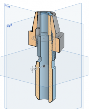
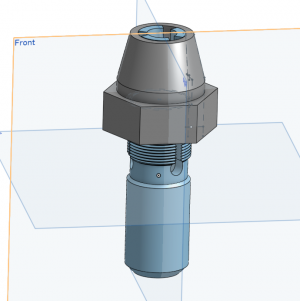
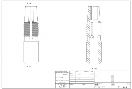
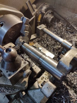
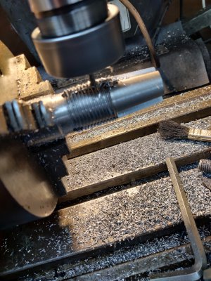
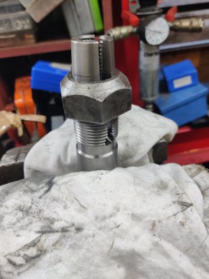
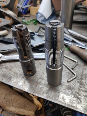
I have a small job on making a few spring dies. These are not for the tool room! They're intended for graunching down studs in a boiler firebox to accept the next size down of sacrificial nut to stop the end of the stud itself burning away.
I'm looking for some input on what type of tool steel to choose for the job. It needs to be tough above anything, doesn't need to hold a razor edge and doesn't need any special kind of heat tolerance as it'll be hand use only. It will need some fatigue resistance and spring as it's intended to form a "contracting die" to get from one size to the next. Heat treatable in the shop with a gas torch is what I'm hoping for, but I'm not averse to splashing out on an oven.
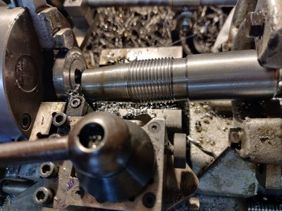
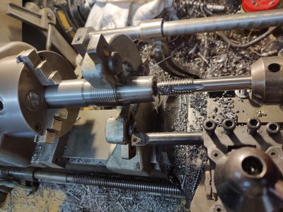
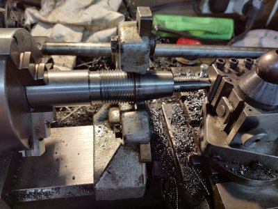
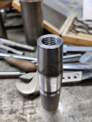
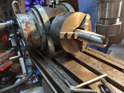
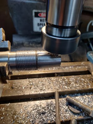
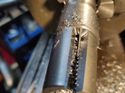
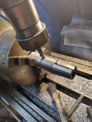
Pics of the original BR 11/16>5/8 tool I'm kinda copying:
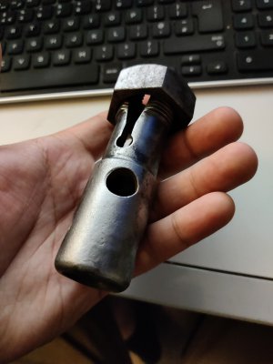
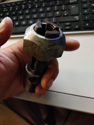
The studs (stays) protrude about half an inch beyond the inner firebox plates. Any rotational forces applied in dieing them down to accept new nuts need to be kept low or you risk breaking the caulking which keeps them steam tight in the plates. The nuts eventually burn away and require replacement, hopefully having protected the stays, but it's not always 100%. You either have to break the corrosion off to accept the same size nut or go down to the next size if there's not enough meat left. You can hopefully see why special tools are needed to get to the point where you can run a traditional die down... They're a bit of a curiousity, being a Whitworth thread form but 11tpi regardless of size, and can be anything from 1/2" to over an inch. I'll be making a complete set or sets. I suspect the originals are just some low grade carbon steel, but I might as well start with something good as I have the choice.
Thanks for reading!
I have a small job on making a few spring dies. These are not for the tool room! They're intended for graunching down studs in a boiler firebox to accept the next size down of sacrificial nut to stop the end of the stud itself burning away.
I'm looking for some input on what type of tool steel to choose for the job. It needs to be tough above anything, doesn't need to hold a razor edge and doesn't need any special kind of heat tolerance as it'll be hand use only. It will need some fatigue resistance and spring as it's intended to form a "contracting die" to get from one size to the next. Heat treatable in the shop with a gas torch is what I'm hoping for, but I'm not averse to splashing out on an oven.
Pics of the original BR 11/16>5/8 tool I'm kinda copying:


The studs (stays) protrude about half an inch beyond the inner firebox plates. Any rotational forces applied in dieing them down to accept new nuts need to be kept low or you risk breaking the caulking which keeps them steam tight in the plates. The nuts eventually burn away and require replacement, hopefully having protected the stays, but it's not always 100%. You either have to break the corrosion off to accept the same size nut or go down to the next size if there's not enough meat left. You can hopefully see why special tools are needed to get to the point where you can run a traditional die down... They're a bit of a curiousity, being a Whitworth thread form but 11tpi regardless of size, and can be anything from 1/2" to over an inch. I'll be making a complete set or sets. I suspect the originals are just some low grade carbon steel, but I might as well start with something good as I have the choice.
Thanks for reading!


