Tool Post Grinding Cast Iron ID/Bore

petertha

H-M Supporter - Gold Member
H-M Supporter Gold Member
Joined
Jan 15, 2016
Messages
994
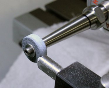
I don't have a lot of run time or experience on my TPG but I'm finishing these cast iron liners which are 0.945" bore x 1.8" long. I've dressed the wheel in-situ. I think its 100 grit but would have to confirm. About 0.75" diameter x 1/4" thick. Its removing material nicely. I rough at 0.0005" DOC (0.001" diameter) and finish at about half that. I'm spinning the grinding wheel at manufacturer recommended rpm for wheel diameter. Lathe is spinning at 300 rpm, direction is reverse to grinder wheel direction. The bore diameters are within 0.0001-0.0002 end for end. So dimensionaly everything seems fine. These need to be lapped anyways so I'm stopping about 0.0005" diameter undersize.

The only thing I'm wondering about is what looks like a pattern inside the bore and lack of shiny finish. It looks worse than it is & hard to photo properly, but hopefully you can see in the pics with the part in the lathe. When I lap with 800 grit (holding up to light pics) no grinder marks are seen. It becomes a constant mat finish in a very short time. But just to show the contrast, the OD was done with no TPG, just basic backed sanding blocks up to about 1200 paper. It looks much shinier. I re-dressed a few times, tried rounding over the edges. Those ones looked a bit better than these pics but generally similar.

I've seen pictures of TPG results that are very shiny but mostly on steels, tool steels, chrome plated bores etc. Even with coarser wheels. Is cast iron different in this regard where its duller or can you spot something I'm not doing right?
 

Attachments

  • IMG_2605_edited-1.jpg
    IMG_2605_edited-1.jpg
    101.6 KB · Views: 151
  • IMG_2623_edited-1.jpg
    IMG_2623_edited-1.jpg
    109.4 KB · Views: 158
  • IMG_2624_edited-1.jpg
    IMG_2624_edited-1.jpg
    90.4 KB · Views: 156
  • IMG_2631.JPG
    IMG_2631.JPG
    5.6 MB · Views: 162
  • IMG_2638_edited-1.jpg
    IMG_2638_edited-1.jpg
    141.6 KB · Views: 150
  • IMG_2641_edited-1.jpg
    IMG_2641_edited-1.jpg
    149.3 KB · Views: 156
  • IMG_2644_edited-1.jpg
    IMG_2644_edited-1.jpg
    99.7 KB · Views: 162
That's a pretty typical pattern for tool post grinding with a long shank. It's the wheel resonating against the work from the vibration cycle of the shank. The shank you have looks pretty stout; if you wanted to improve it further, shorten it to the shortest it can be to reach the work. Adding mass with a heavier wheel will damp the radial phasing of the system, helping the finish. My TPG is a Do All Midget, as it's name implies it has a 1/4" spindle that leaves some amount of patterning no matter what I do. It doesn't seem to hurt anything beyond cosmetics, so most of the time it doesn't bother me, but when it does, shortening the arbor and running as big a wheel as I can fit into the work has improved the finish.
 
Last edited:
Hardening the shaft may reduce the total deflection (by changing spring constant)...

Hardening steel changes yield strength but not Young’s modulus (stiffness).
 
Hardening steel changes yield strength but not Young’s modulus (stiffness).

D'oh! But Young's modulus does change numerically, even if the ratio doesn't, because the elastic/inelastic modes move after heat treating. At least he'll end up with a shaft that's harder to bend. Edited silly heat treat idea.
 
D'oh! But Young's modulus does change numerically, even if the ratio doesn't, because the elastic/inelastic modes move after heat treating.

I don’t follow this statement. Can you clarify? AFAIK Young’s modulus (the slope of the stress-strain curve for elastic deformation) does not change.
 
Relax, I'm not the first to confuse strength and elasticity. Luckily I still know how to grind.
 
Yes the rigidity of the grinder shaft crossed my mind too. The black felt pen line you see on the tapered shaft is the (~2") depth when the wheel exits the back end of the part so its the shortest shaft I can use. Actually making a non-tapered shaft with larger diameter was exactly what I was thinking. For example 0.70" diameter shaft holding a 0.75" wheel, which would make the wheel about 80% of the bore. I think there is some preferred stone/bore relationship along those lines. Obviously the tapered shafts are for smaller stones like in the 1/2" range but therefor are prone to increased deflection. I found it was worth doing a spring pass like a boring bar, but at most was never more than 0.0002" taper from front to back. I also changed the feed on the finishing pass but OTOH its not really like single point boring is it where you want to cut over the hill tops at a different feed, is it? The grinding wheel is completely random between stops & starts.

One kind of PITA factor is the Themac spindle taper is their own recipe. It doesn't match any commercial taper. I did make a few test blanks which I got to fit pretty close by mimicking the shaft with DTI along the taper. I just figured I would try the included shaft first before introducing a new potential variable of a taper not quite fitting right. What do you think material wise, something like 4140? I have had good results with 1144 SP (stressproof) steel which seems to be very stable after machining. I don't have heat treating facilities.

What about the aspect of the 1/4" wheel? Does that seem ok? I've seen lots of 1/2" wide wheels but then it gets kind of ambiguous. Some guys relieve the back half which essentially turns it into a thinner wheel. Some guys dress it in-situ along the lathe axis, then give the TPG a slight offset angle, somewhat like cutting tool relief. But I'm not clear if that's material dependent, personal preference, TPG power dependent... Seems to be getting to be a black art. All I know is I've seen guys doing some amazing work on chrome plated liners that look shinier than my CI. Again, not that I want shiny on this particular application, nut more about learning how to set up properly.

What the Themac extension spindles look like. They actually get much longer than the shorty I'm using.
 
Rigidity is what I've blamed my problems on. I think I've gone down a similar path with stone grinds and such. I think you may have a chance to improve the finish by matching the surface speed of the lathe work to the surface speed of the grinder so that one isn't dragging or skipping over the other. Themac looks to be a good grinder, and the arbors seem nice and stout. I have tried different angles of dress, but have settled on a perfectly parallel dress on the stone. It will naturally wear a taper as you work unless you infeed at both ends of the work, but I think beveling the stone actually reduces the amount of abrasive in contact with the work, effectively turning a 1/4" wheel into a 1/8 wheel, for example. The width of the wheel you can use is going to be limited by the power of the grinder motor, and a bigger contact patch provides a more uniform grind. A beveled wheel will leave you chasing dimensions as it wears and its diameter shrinks. So, match speeds and try to maximize your contact area.
 
Can you elaborate on 'matched speeds'? Right now I'm on the pulley configuration giving 22,000 rpm recommended for 0.75-1.0" stone range. Lathe spindle is doing 300 reverse direction so I guess that means 22,300 effective?. My stone is maybe 0.7"diameter. The next available combinations are 11,500 recommended for 1.125-2.0" stone range or 34,000 for .375-.625" stone range.

I should also mention the part is not even warm at the rate I'm removing. I think the stone is 100 grit aluminum oxide. I'd have to check details but I think the material coverage for wheel (type) included cast iron or similar hardness steels. I'm not using fluid, it just seems to make a mess. The little powder that is produced seems to just vacate out on it sown because I have the spindle blocked off just to prevent dust from getting in behind the collet chuck so maybe it has a bit of natural draft. The stone never looks clogged. I was thinking of going finer yet but what little info I could find suggested this isn't necessarily the best thing as the heat can go up.

Well this particular job is essentially done so now I have time to experiment with the variables. Was wondering more than anything else. When i see practically anything come off a surface grinder, it looks shinier. But OTOH that is usually a more rigid setup, typically tool steels. I don't have a good handle on what CI looks like off a grinder. All I know is my OD finished to a mirror so its achievable.
 
I bet the grind finish pattern would change quite a bit if you doubled the lathe speed. Like tuning an old TV to get a picture among interference, certain windows between frequencies will be clearer than the nominal setting.
 
Back
Top