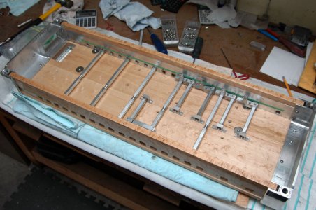
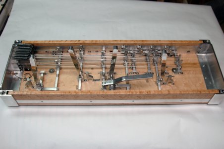
The Pedal Steel Guitar

BenRom

Registered
Registered
Joined
Oct 22, 2012
Messages
12
I would like to start a new thread describing this hobby of mine making the pedal steel guitar.
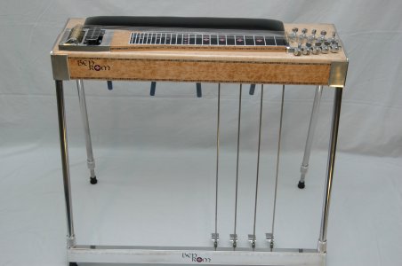
I'll start off with a full pic of the pedal steel and name some prats so you all have an idea of what's what.
I started a thread earlier but t fell by the wayside as threads often do when we get busy with a project.
Here you see the BenRom pedal steel guitar, so called because you play it with a steel bar in your left hand and also, more importantly, with a series of pedals and knee levers that are used to change the pitch of the strings to a tuneable note.

In both ends you see the aluminum plates that cover the end of the wood body and wraps around the front and back. They are called the ENDPLATES. On your right you see the tuing keys that are attached to the KEYHEAD. On the left side you see the rounded brass pieces. They are part of the CHANGER which works together with other parts to change the pitch of the strings.
The aluminum plate that wraps around the changer and the electro-magnetic PICKUP is called the TAIL PIECE or the CHANGER HOUSING.

In the lower extremities we have the 4 legs, made out of stainless steel and are height adjustable. These are one of the few parts I don't make myself.

You also see the PEDALS attached to the PEDAL RODS which change the pitch of the strings, as well as the KNEE LEVERS that hang down from the wood body and are barely visible in this pic.

I will try to get on this thread more diligently and post more and detailed pics as I have time.
DSC_0004.JPG
Hope you will enjoy it!

DSC_0004.JPG
 
A while back I saw on one of those "How's that Made" type shows a quick version of the manufacture of steel guitars. Fascinating. Never would have thought that there were as many moving parts involved.
 
Very nice! I'd love to see more of your build details for those.

Thanks much,

-Ron
 
Thanks for this, and I look forward with great interest :))

Dave
 
Might as well go to the part that I find the most difficult to make.
Due to the fact that I am in my mid 60s and been trying to learn machining the last 2 years, this part becomes quite a challenge. There are so many slots, ledges and holes that have to be machined to as close a tolerance as you can muster and for an older fella to switch from woodworking to machining down to a tolerance of say .005 can become nerve wracking. Not only does one 2X4 of 6061 T6 cost $35 but one bad cut can result in 2 days work down the drain.
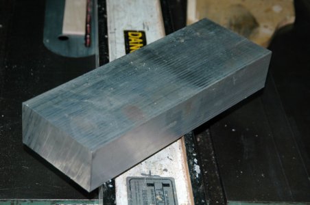
Pictured here is the raw piece of 2X4 about 11" long. I hog out the most of the aluminum with a solid 1" end mill. The finishing cuts are made with a 1/2" end mill.
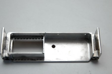
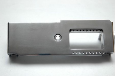
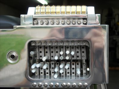
This endplate is for the changer end of the guitar and houses the changer fingers where you see the "raise and lower bars". This is the finished end plate before polishing.
the top row of holes is for the "primary raise tuners" and the bottom row is for the screws that attach to the "lower return springs" which have adjustable tension. The springs are hooked on to the "lower bar" and are used to hold the lower bar in place when activating the "raise bar".

The round hole in the middle of the end plate is to fasten the phone jack that is the outlet for the pickup

Also on the lower side in this pic we can see the leg holes which are drilled on a 10 degree angle and tapped with 1/2- 13 tpi
This operation is all done with the mill, with the head set at 10 degrees; first the shallow counter bore for the leg, then drilling out the hole for the threads and finally the threading.
This is the first operation done while there is still a lot of "meat" for the vise to hold on to. It eliminates chatter and vibration.


www.benrom.com


More details as we move along...

2X4.jpg


chgrendpl~ins.jpg

Chgrendpl~outs.jpg

chgrendpl~ins.jpg Chgrendpl~outs.jpg 2X4.jpg
 
Last edited:
That is indeed a nice chunk of material with a nice amount of work going into.

Nice job- do you have any other pictures at different angles to show it off a bit more?

Dave
 
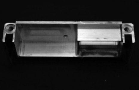
Thanks Dave. The end plate really only has two interesting angles - the inside and the outside. But here are a few more photos - one where you see the leg holes, the next one where the end plate is mounted in the cabinet , with a fairly clear view before all the clutter is added, and after things are in place and finally a close-up of the "changer window" as we call it, showing the raise and lower plates in place(the ones with three holes each) and, from bottom, the tension adjusting screws for the lower return springs and last in the top of the window you see the row of 10 socket head screws "primary raise adjusting screws".

Endpl~Ins~bot.jpgAssemb~bot.jpga.JPGChgrWindow.jpg

Endpl~Ins~bot.jpg Assemb~bot.jpg a.JPG ChgrWindow.jpg
 
Ah, thank you, those pics help show exactly what's going on there, thank you, and you're doing fine work!

Dave
 
Wow, really, really cool. I really appreciate the mix of crafts you are displaying. How much variability is there in the internal workings from one instrument to the next?
 
Thanks all, for your kind remarks. Answers to a couple of questions...Tony, the How It's Made segment was Ed Fulawka of Fulawka steels here in Ontario. He is about the only one doing this in Canada on a full time basis. The man is going on 85 and still spends 6 hours in the shop every day.

Building Something...I try my best to keep zero variability in the inner workings. Although this is difficult for an amateur machinist like me, things like changer mech pivots and bell crank hole spacings should be kept as uniform as possible to ensure the same "pedal feel" and ease of operation.
I have discovered it is near to impossible to get the same measurements down to say .005" from guitar to guitar. I chalk it up to age and inexperience.

Any tips would be appreciated as to: When I measure something that is in the vise and get a certain measurement and then un-clamp it and measure again..the measurement can be smaller by 6 or 8 thou. How do I achieve better consistency? Or, should I be happy with being as close as that?

Another thing...I put the micrometer on the table say to widen out a slot from .495" to .5" only to discover that the slot ends up being .503" maddening in the least! I don't have a DRO as of yet. Maybe that will make it easier for me to be right on?

It is tough with a manual mill for sure. CNC and knowing how to program it is the only thing that makes consistency the way I see it.
 
Back
Top