The New South Bend 10K

No takers on the ground question????

I have everything wired up and tested!
30196964264_1d355ce885_h.jpg

30792073186_e2e623b920_h.jpg

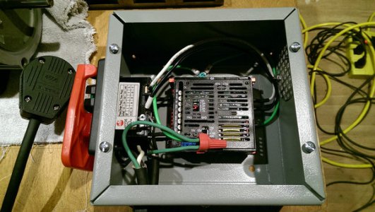
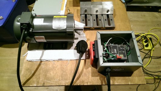
This control seems really great. When I switch from FORWARD or REVERSE to STOP, the control brakes the motor to a stop in about 1 sec. If I open the enable switch it stops much more quickly, like in 0.2 sec. This will be great for the ESTOP. The large switch you see mounted in this box will be the main disconnect.
More will be forthcoming!
R
 
Thanks John! I will read more about that.
Robert

After reading about this issue I will only be grounding one end of the shield to prevent a ground loop. I suppose I will ground the end at the controller.
Robert
 
Last edited:
Thanks John! I will read more about that.
Robert

After reading about this issue I will only be grounding one end of the shield to prevent a ground loop. I suppose I will ground the end at the controller.
Robert

It is recommended to star ground all grounds including shields. It is correct to ground only one end of a shield. I prefer to use din rail and din rail connectors. Sometimes it is difficult to connect shielded multi-conductor cables to a star ground because of their location on a terminal strip. In that case I add grounding terminals as close to a star ground as possible. Din rail ground terminals are essentially chassis grounds and have very low resistivity so inducted eddy currents and ground loops are minimized.
 
Thanks John! I will read more about that.
Robert

After reading about this issue I will only be grounding one end of the shield to prevent a ground loop. I suppose I will ground the end at the controller.
Robert
Connect the shield to the COM terminal of the controller and nowhere else. Ground the case of the controller. COM will be connected to the case internally if that's appropriate.
 
There are different debates on shield grounding, and sometimes it is more empiric based, and if you are having problems. Convention is usually to star ground at the source/controller and float (not connect) the other end of the shield. On VFD installs I have seen arguments to ground at the source and alternatively at both ends, I use the latter. On the other hand, I had a situation where a tachometer display went crazy when I grounded the shield at one end, and it would only work if the shield was left floating at both ends. I believe the shield grounding picked up the VFD noise on the machine and induced it back into the sender wires. I would follow the manufactures guidance, and if you have noise problems, then reevaluate the shield grounding.
 
Manufacturer says not to ground the shield at all. Also says not to ground any of the terminals. It does not mention tying the shield to COM although that makes sense. I have created a star ground in the box. I think I will start by grounding one end of the shield there and cut it loose if I have problems. I'm hoping this control is not very sensitive to noise. It's not a device I want malfunctioning! ...Like the lathe coming on when I 'm not expecting it!
I really appreciate all the replies as they are very educational all the way around.
Robert
 
Like many of us here, I'm not big on following directions unless I agree with them! :)
R
In this case it is best to follow them. In many controllers the COM is connected to the power line neutral. In some it is even connected to the negative side of a full-wave bridge connected across the line.
 
Back
Top