The earth wire really isn't required for electrical operation. The stepper will work without it connected. It is only (and a valid) safety precaution. You are dealing with relatively low voltages. The problem is elsewhere.
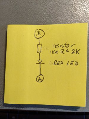
You need to see if 1) you are getting valid pulses from your rotary encoder, 2) if you are getting valid pulses to the stepper motor driver and 3) if the polarity is correct for the driver enable. With a multimeter, it will be awkward, but you can test for some of it. Another thing you can do is to attach a LED with a series resistor as a make shift test probe. Kind of like this:

The resistor can be a 1/4W or 1/8W between 1000 ohms and 2000 ohms. You don't need a lot of current, this is just a probe. Connect (A) to the processor ground. Point (B) is connected to the point on your circuit you want to test. If the point is 3.3V or 5V, the LED should light up. Depending on what LED you use, it might be dim, but it should be visible. If the test point is "low", then the LED will not light up. A little 3mm LED is fine for this.
You need to connect this point (B) to the A and B inputs of the encoder to the TI board. As you turn the encoder very slowly do you get the LED to light at all? Is there a spot where it is brighter than usual? Is their a spot where the LED is dark? Do you have the required pull up resistors for the rotary encoder installed? I think you can do this same test with a multimeter, but multimeters are not quick responding, so you may get confusing information.
One thing that can trip people up is the ENABLE signal to the stepper driver. There can be reverse logic to deal with. I don't remember which is the correct polarity, high or low, that turns it ON, but I do remember getting confused about it and maybe having to invert the signal. I think there is a provision in the code to do this. Which logic level actually turns things on depends on the actual circuits on the Clough42 boards, and the driver board. There maybe multiple logic inversions, due to the buffers that were chosen. So I would measure the actual voltage on the driver board and see what it is.
These driver boards can be confusing for their inputs. There are multiple ways that would work and not work. The way I recommend is to connect the + inputs to +5V (might be able to do it with +3.3, but I haven't done it). The - inputs are connected to the control signals. When the - signal goes low, (as in ENA- goes low) current flows through the driver's optocoupler LED, and it turns on the optocoupler's transistor, which goes low. When the - signal goes high, no current flows through the optocoupler LED, so the opto transistor turns off, which means the internal signal goes high. This is the inverted (reverse) logic that I mentioned, and it often confuses the daylights out of people, including myself at times. Many times the processor does not directly drive the optocoupler, because the I/O pin cannot directly drive the LED, so a buffer is used. Sometimes this is an inverting buffer! So a simple software logic inversion is often a lot easier to try than trying to fathom all the physical circuits...
If the encoder is generating valid pulses, you should get pulses generated to the stepper driver. They might be inverted, but you should get some output. I'd check the encoder is functional first, because if the processor cannot detect spindle position change, there will be no commands to the stepper.
I hope this is at least slightly helpful. It's likely that you have a simple miswiring, or a logic inversion that is needed, rather than a big problem. It can be terribly frustrating to figure out. A bit of perserverance, and some measurement of actual voltages at various points can help you identify the issue. Don't assume anything - just measure the points and see what it tells you. Then work back from there.


