Starting My CNC Journey for PM-25MV Mill

I've been playing with FreeCAD and think I'm getting used to the CAD part (Part Design workbench). Now, I'm trying to get the Path workbench running. I think I found a limitation. I have a 12" X 6" X 0.188" piece of Plexiglass (Acrylic) that needs 12 holes drilled into it of two sizes. I got that working.

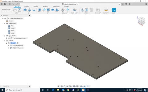
It also has a 0.750" deep by 2.930" cutout in it. I want to use a 1/4" endmill so I get a 1/8" radius on the internal corners. FreeCAD won't let me mill out just that area. It wants to go around the entire perimeter even though the piece is cut to final size. Obviously, I can't do that since I need to clamp this down on the mill table. I just want that cutout milled. I read a little and it seems this feature was removed a few revisions back. So, other than hand editing the G code output, what can I do?

I should leave this to somebody who actually uses that particular program, but generally, you can:

1. do a partial "open" chain of the feature.
2. You can sketch lines that can then be selected later as a machining boundary (which you should be able to keep the tool inside, centered on, or outside of). "Avoidance", "Air" and "Containment" are other names I've seen for features to help control a toolpath like this.
 
and a final last resort option is to edit the resultant G-Code to remove the parts you don't want. Most likely there is a way to tell your CAM software what features you want to mill.
 
So, I'm going through the same design in Fusion 360 and I'm having a similar issue with the CAM part. I can't get the software to only mill out the cutout. What should I be using? 2D Adaptive Clearing? 2d Contour? Or, some 3D method?
 
Most likely 2D adaptive clearing (I would need to see the part/feature to give better direction), but again you need to sketch some lines and use the said sketch lines as a machining boundary to limit where it will cut.
 
Here is an example.

The 2D adaptive path for this particular part wants to do all of this when left to its own devices.

jQ8nx1j.jpg


So I drew a rectangle to limit it. (note the two smaller rectangles up top, more on that later).

YL29sqG.jpg


Selecting the rectangle as a chain under the "stock contours" section will get you a yellow line that looks like this. The blue area shows what will be cut.

FTkd2i3.jpg


The ensuing toolpath calculation. I forget why I did this, probably had clamps in the way or something.

LpPiEjR.jpg


Back to the two small squares from the above picture. I used those in a 3D parallel toolpath to restrict machining area for these the fillet radii (was being lazy and didn't want to do the extra setup to mill them the conventional way).

36JaeIy.jpg
 

I would definitely use 2D adaptive for that. Another thing that springs to mind, that may or may not matter in this case ... but is a MUST know for Fusion.

When you select the contour you would like machined, click on it ... then click on the same line again to open up the custom dialog box. For some reason, screenshots are not capturing it for me so here is a link that explains it pretty well. Anyone just learning Fusion 360 has little to no chance in figuring this out on their own, and it would be a struggle to use the software without it.

 
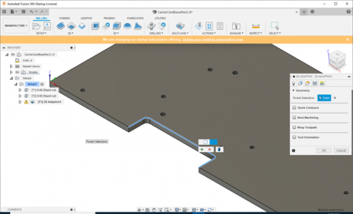
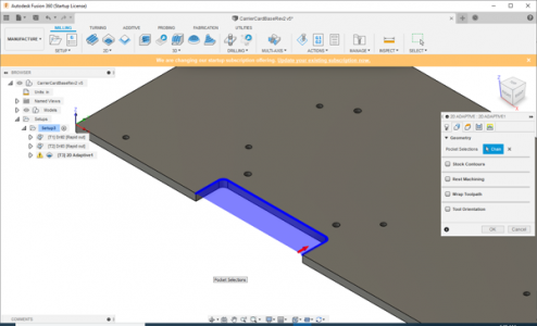
Okay, I'm getting closer. But, I'm getting an error about "empty toolpath" after doing this selection.

As you can see, I have made the proper selections and chose Open.
Fusion2.png

The correct area is highlighted, but I still get this error about empty toolpath.
pic3.png
 
Try either offsetting your bottom height, or reselect the contour on the bottom of the part. Right now it looks like X and Y area is sorted, but it has no Z depth information.

The empty toolpath warning is very unhelpful, so generally I go in and change 1 thing at a time until something generates, then tweak it to my liking from there.
 
I got past the empty tool path error.

I'm still trying to decide which way to go: Fusion 360 or FreeCAD. They both are not easy to learn. I do like the idea of having the CAD/CAM software on my LinuxCNC PC.

FreeCAD has its issues too. I don't know how to only select certain areas to contour. It may not be possible.

I've been reading that Fusion 360 seems to be moving toward charging for hobbyist. If that's the case, the decision is easy.

I have my LinuxCNC PC up and running now with the ASRock Mini ITX DDR3 1066 Q1900B-ITX MB, 240 GB SSD, and 16 GB DDR3 RAM. My jitter numbers are good under 16,000.
 
Back
Top