Spindle RPM gauge? PM-1236

mike96

Registered
Registered
Joined
Aug 16, 2011
Messages
63
I did a brief search in this forum earlier today. Has anyone done a generic spindle RPM meter on their lathe, specifically the 1236, but any installs will help, I am just looking for ideas on how I want to mount the magnet and pickup. I am not real thrilled on the idea of drilling a hole in the tail end of the spindle and would rather not put it in a position or orintation that may cause the magnet to fly across the room if it were to come unglued. Just looking to see what others have done to get ideas.

Thanks.
Mike.
 
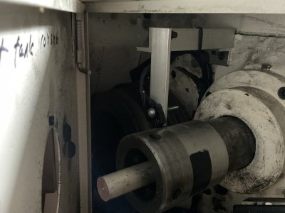
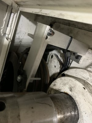
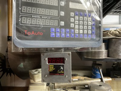
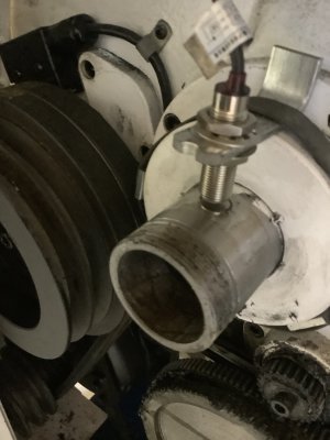
This is my PM-1236 with the MKCtools.com unit.
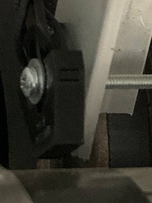
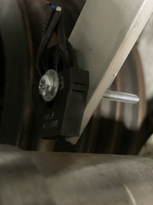
I used 3/4’ aluminum angle to mount the sensor. The pics are not the greatest but I would have to move things around to get better pics. Let me know if you can’t make heads or tails of it and I’ll get better pics for you.

IMG_0320.jpegIMG_1588.jpegIMG_1591.jpegIMG_1592.jpegIMG_0319.jpeg
 
No worries. I get the general idea. My kit is a bit cheaper (Ok, a lot cheaper) but the angle alu would work for mounting my pickup. It would easily put it in a position to where I can get it close enough to the spindle for the magnet on my original idea. I was thinking a slip fit ring with a couple of set screws to hold it in place and a pocket in the face of it to hold the magnet. My brain just didn't want to let me figure out how to mount the pickup in a way that didn't make the ring 10" in diameter...

Thank you for the reply
 
I think it is worth pointing out that the tachometer used by Z2V above employs an optical reflectance scheme with an LED and a photodiode. As such Z2V was only required to put a piece of black tape on the back of the spindle. No mounting of magnets on rotating parts.
 
  • Like
Reactions: Z2V
Last edited:
I had the same concerns. Just used a standard setup and been using for about a year without any problems. Think I did use drop of superglue on the magnet. As extra precaution put a strip of clear tape over magnet. Don’t think this was probably necessary.
 

Attachments

  • IMG_0312.jpeg
    IMG_0312.jpeg
    277.1 KB · Views: 39
Sweet. Thank you everyone for your pics on how your RPM pickups are mounted. I have an idea on how I will probably do mine. I am sure it will still be why over complicated knowing me but that's okay, it will give me a chance to play with the mill and the lathe... I appreciate all the input.

Mike.
 
The end of the spindle is threaded for the spider, if you do not need the spider you could make something to use those threads to hold the magnet....
 
Hi @mike96

I have the PM1440GT. While doing my VFD conversion, I put in a rpm meter. Did it a little non-conventionally in that I put in 10 magnets and get 10 pulses per revolution. I did not really need this, but it allowed my to use a small digital rpm counter display which would fit in the front panel rework. This then gives you a count of 10 per revolution, but the counter has has extra digits so is no problem. Later, I also connected a counter to this same sensor so I can get a reading of how many revolutions the spindle has turned. Actually it is how many 1/10 revolutions, which is nice if you want to track the phase of the spindle as you turn it by hand. It works down to DC so you can turn it by hand and see it count. So the magnets are mounted in a nylon ring which leaves room for a spider to be built into it later. The ring (green) is split on one side, slips over the spindle, and then has a nylon screw that allows the ring to be tightened down/clamped very securely to the spindle. There was already a spare threaded hole near the spindle and this is what I used to mount the Hall effect sensor.

I will link to some pictures as well as to the extensive description I provided of the VFD conversion which includes the rpm meter. Grab the description "PM 1440GT Part 2 VFD..." pdf document for a full explanation of the conversion as well as a parts list. I added the counter later and is not in this write up but info in posted later. To see the picture of this go to the posting #21.
VFD conversion using solid state electronic components.

Another project using the backer board that I built for my lathe VFD conversion is the RMP Hall Effect magnet holder.

Good luck and have fun!

Dave L.
 
Last edited:
Back
Top