

- Joined
- Oct 12, 2023
- Messages
- 40
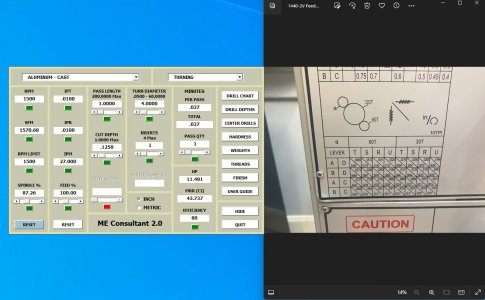
Just to make sure I'm using this correctly. (Screenshot included for clarity)I use a machinist calculator https://www.softsea.com/review/ME-Consultant.html
After inputting material and tool used, set your max RPM. It will then give you starting feed. Play with it from there.
Not positive, but I think it just scales down feed linearly to keep chip load constant.
1. I opened the tool, selected Aluminum then turning.
2. The automatically generated values populated based on the default parameters in the tool.
3. I changed the "RPM Limit" to a value of 1500 then clicked on the green square which changed everything based on my added rpm limit.
4. Which gives me a value of .0180 IPR
5. On the lathe with the 60T gear I would set the levers to "BDU" for a value of .0164 then work up from there until I get satisfactory chips. Or I could use the "BDR" for a slightly higher IPR.
Does this look correct? I know this may seem elementary to some, but I'd just like to make sure I'm doing everything correctly on my end. I was having some issues using the Machinery's Handbook to find speeds/feeds for some 12L14 I was practicing with. All of my calculations from there had suggested RPMs way over my machines capabilities. This calculator would solve that problem.
Attachments
Last edited:


 .
.


