Small Chronometer Box

It happens. I replaced a chip this morning that I swore had a bad output. Turned out to be a software issue in handling start/restart on one of the the I2C busses.

One thing a bit obnoxious about the Raspberry Pi Pico, you hold down a button on the gumstick module while powering it up to load code. At that point it basically acts as a USB flash key and you drag and drop your program. Standalone that means unplugging and plugging the USB back in to power it up. When interfaced to a more complicated board that has a separate power source (other than the USB), you need to turn that power off or it will keep the pico from powering down. But as soon as you load the code (by drag and drop) it runs that code so you want the external power on for initialization routines. Makes it a bit tedious to do it all correctly. One solution is to use the three line debug interface hooked to a Raspberry Pi host, just haven't done that yet. Another is to reflash it to the Arduino IDE.
 
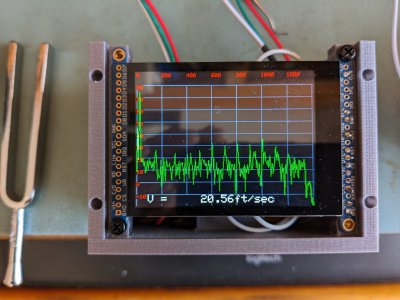
Some progress. At least things are alive. The 5lbs of junk is in the box and the display fits. Tested the radar with a tuning fork and the detected "speed" came up. At X band a 440 Hz tuning fork should detect as 20.56 fps, give or take. 440 Hz tuning forks aren't always on frequency, depending on how you whack them. They are close, but not exact. At least the ones I have. My audio testing has also confirmed that. The horizontal axis is in feet per second. The Y axis is in dB, because in radar there is way too much dynamic range for a human to comprehend or see. Each grid line in the dB scale is 10 dB.
PXL_20221213_155416702.jpg
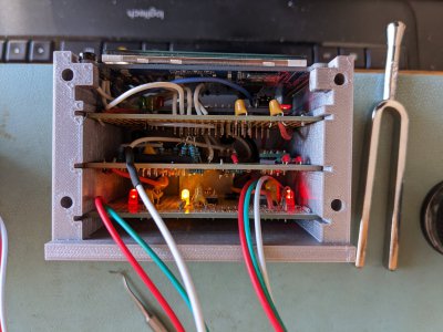
Here's the stack of boards. If I ever get around to it, I may spin a PCB for this. At the time, I couldn't fathom KiCAD so never pursued it. Now at least, (with a PCB designed in KiCAD) I think it could be possible. Power supply on bottom, next up the 7 pole Chebychev active filter, then the Feather M4 Express mounted on it's own PCB, and a display breakout. About a year ago, when I last had it on, a tantalum cap exploded. That was kind of exciting. It was just a defective part. The polarity was correct. The voltage rating was 16V and there was +5V on the part. Buying off-shore components can be a crap-shoot. Counterfeit parts abound.
PXL_20221213_161053797.jpg
I have to redesign the wall thickness for the holes on the top near the display (see first picture). Not enough meat on the walls to prevent insert blow out. The holes for the cover plate for the board I think are fine. Oh, the USB cutout is way off. Totally miss-estimated that. That's the primary reason for me assemling this, to get a better feeling for where the silly actually is. Not having a mechanical drawing for that board, has me at educated guesses and a little mensuration.
 
Ok, the CAD work was done last night, and a couple pieces were printed then. Today the section of the housing, similar to the picture above was printed. Just cleaned out the supports and the holes so I can see what I have. Think I will do the basic fit check again, this time concentrating on the USB port. For some reason, I get to design it in mirror image mode, which is tough to get right. I look at the part in the -XZ axis, but have to design it in the XZ axis. It occasionally mixes me up. The key walls are a little thicker so I think I can get all the inserts in.
 
Arggh. The twelfth and last insert is off. I must have leaned the wrong way or something. The hole doesn't line up. Unfortunately, it is in the 6.5 hour print. Well, I'm just going to leave it be for now. Structurally, I don't need four screw. The USB connector port is pretty close, so that is good. and the hole for the display is just right. The cable exits are kind of lame (half circles, aka mouse holes) but they should be fine. I might RTV that so crap doesn't fall in. Is there an RTV like material that is compatible with PLA?

If I have to change things, maybe I will print a new box. Think this could use an on/off switch... I was just unplugging the external battery. A switch would be easier. But overall, this came out pretty well. It fully encloses everything. I can reprogram it, if I need to, by sticking in a USB cable

Now that I am playing with it, I see a bug. I think I can fix that. Toggling fps to m/sec leaves artifacts on the display. I've learned a bit about graphics since three years ago.

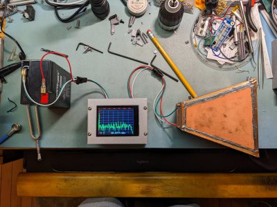
This box sort of looks like a real thing. That's pretty neat. I like this. The microwave assembly on the other hand reeks science fair. Oh well. Sometime I will clean that up as well. For now, it is satisfactory. Honestly, I need to have a coax cable for the signal. I have a simple wire, not even a twisted pair. But even with that, it detects pellets pretty well.

PXL_20221214_231516068.jpg
 
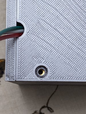
Missed it by that much. Frustratingly close! It it hadn't been countersunk, I would have just dragged the hole.
PXL_20221214_235821050.jpg
The holes were on center as printed. But somehow I had some slight motion towards 4 o'clock when I installed the insert. Drat. The printing is not so good on this surface either. Weird pattern. That is the steel sheet side.
 
Missed it by that much. Frustratingly close! It it hadn't been countersunk, I would have just dragged the hole.
View attachment 430004
The holes were on center as printed. But somehow I had some slight motion towards 4 o'clock when I installed the insert. Drat. The printing is not so good on this surface either. Weird pattern. That is the steel sheet side.

I know the feeling. It sucks.

The longer it took to print the part, the worse it sucks.

I only go about 3/4 of the way in with heat set inserts, then I linger for another 5 seconds ish with the insert a little proud, just to add heat.

Then I push it the last 1/4 of the way in, strait down, with a 1-2-3 block, gauge block or something. They seem to align better for me and end up nice and flush with the top of the part.
I set my soldering iron to 439F (215C) and slowly push in the insert. Like I said, got 11 of them, but fudged the twelfth. I usually use some surfaces as a visual guide, but it's basically a hand operation. And apparently old WobblyHand isn't too steady after a while.

You'd think there would be a method to slide the insert to position and plastic weld/fill the hole. I have just the machine for filling the hole - think it is called a 3d printer. Would be nice to be able to do this, perhaps with a camera at the nozzle and a joy stick. Push a button and filament comes out and into the hole to be filled. Move the extruder aside and smooth out with a tool.
 
Back
Top