Small Chronometer Box

WobblyHand

H-M Supporter - Diamond Member
H-M Lifetime Diamond Member
Joined
Dec 18, 2019
Messages
6,527
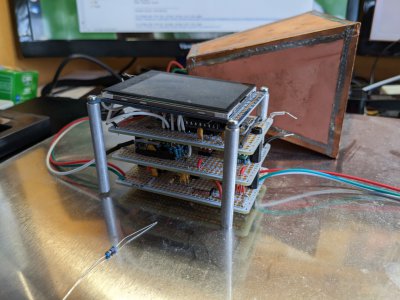
About 3 years ago I built a doppler chronometer out of an eBay X-band doppler module, a home brewed analog front end, an ARM M4 Arduino and a touch panel display. Got it to work ok for my use. Used the knowledge gotten from programming the display, in my ELS project. The chronometer will detect pellets being fired up to 1200 FPS, if I recall correctly. Anyways, it has always been a pile of stacked PCBs and stuff, and never had a proper enclosure. Thought I could rectify that by designing a printed enclosure for it.

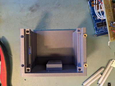
These boards have terrible mounting on them, there's only 2 holes in the prototyping cards. So I designed a sort of card rack where the cards would slide into their respective slots. Looks kind of like this:
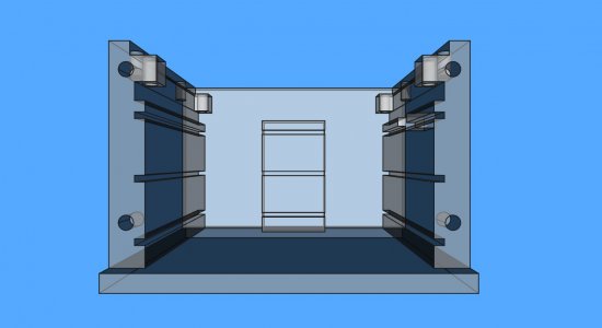
rearviewchronybox.jpg
Up near the top, you can see four tab like pieces sticking out that will hold the display. I designed the tabs to accept thermal inserts. The unit is closed up by a cover on the front and the top. I think my best hope of printing this is the back piece sits on the sheet. That way I only will need supports for the tabs and nothing else. The display cover and front cover will be printed separately. Here is the view looking into where the stack of PCBs would be and the display on top.
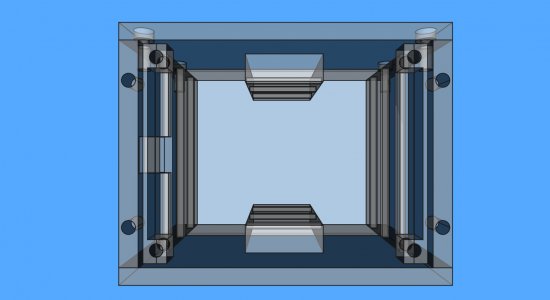
topviewchronybox.jpg
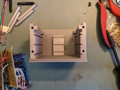
The parts that are sticking out top and bottom retain the PCBs from rattling around. Finally, I added a cover that allows the display to viewed.
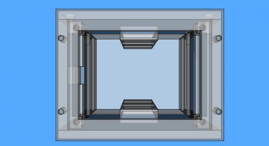
topviewwithcoverchronybox.jpg
I sliced the first photo using 0.20mm SPEED with supports everywhere at 15% infill and the print time comes out to be 6h 7m. Overall dimensions are 95 x 75 x 65 mm. Is there some way to reduce the print time? Or is this just what happens with something of this complexity and size?
PXL_20221210_190707075_1080.jpgPXL_20221210_190727193.jpg
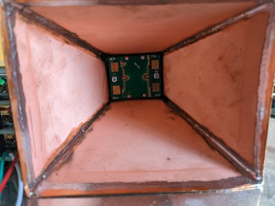
Yes, I scraped off the coating on the antenna elements. Got a few more dB sensitivity.
 
Using that new Prusa to good effect.

Something tells me, you'll never be without a 3d printer again. The tool you never knew you needed.
 
Using that new Prusa to good effect.

Something tells me, you'll never be without a 3d printer again. The tool you never knew you needed.
You are right! Wish they were faster though... Six hours for a dud isn't motivating. I do try to learn from the mistakes, and save some of them to practice stuff, like inserting inserts, but I am collecting a small pile of junk... Is any of this stuff recyclable?

Was just sitting around today thinking that maybe it would be a good idea to package that chrony up. It's been so long since I fired it up, that I misplaced a special USB cable that I had to buy with a long snout. The reason for the snout was the stupid mounting screw was in the way so a normal USB cable wouldn't seat. Now that I can print stuff and or machine things, I don't have to put up with that stuff. Won't need a screw in that location any more.

The real enabler for me was learning 3d CAD. I only taught myself this this year. Still making a bunch of silly mistakes here and there, but overall can get most simple stuff done. I looked back at this year and was pretty amazed at the stuff that I modeled and built. Made me smile.
 
You are right! Wish they were faster though... Six hours for a dud isn't motivating. I do try to learn from the mistakes, and save some of them to practice stuff, like inserting inserts, but I am collecting a small pile of junk... Is any of this stuff recyclable?

Yea, they sure are slow. My new Voron has more than doubled my print speed, and it's still lots of overnight prints

I'm sure it's recyclable, if you mean, dropping it in your curbside recycling bin. :grin: The PLA is even biodegradable.

But, if your asking if there's a way to turn it back into useable filament, I have no idea.
Slow is the word...

As for recycling, sounds like a round tuit project! Make a cylinder, a die and a piston, wrap it with nichrome wire, heat it and press out new filament of the right size. Oh cool it and wind it up as it comes out! The winder would be interesting. Sounds like an interesting multiple discipline project, but not now...

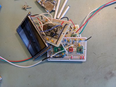
To get back on track... I have some M3 inserts that I am going to try installing. Unfortunately the box wall thickness is not enough in four locations. I only have 0.75mm on two sides. Going to be a bit dicey. Probably will blow out the walls. We'll see. Otherwise, the print came out surprisingly ok. The cards fit the slots, the holes are in the right places for mounting the display. The only thing I haven't checked is the USB connector location. That could very well be off center. The Feather M4 did not center the connector to the card. The connector is approximately centered, you might be able to see that in the photo. The M4 board drawing supplied doesn't dimension the location. So I measured it, but I'm sure it's not quite right. I don't want to model my circuit cards or the M4 board as the returns are diminishing. The circuit cards are hand assembled with wires and solder. So the best I can do is move a few wires away from the edges and hope for the best.
PXL_20221212_185254888.jpgPXL_20221212_185314821.jpgPXL_20221212_185352673.jpg
Red board is a carrier board for SOT23-6. Not my first choice for a part, but that's all I could get. I've had to use DFN8's before at home, they are 3 x 3 mm. You have to use solder paste and hot air, no other way to solder them. No leads or pads on top. Did all my soldering under a stereo microscope, that's the way to go, in my opinion. The OP amp doing the hard work is an LT6238, selected for it's low noise, think it is 1.1nV/root Hz.

Going to be a bear to wrangle this all in the box. 5lbs of you know what in a 1lb box. The hope was to fix any wires near the edges and coax the cards into the slots, occasionally tapping with a LFH :D
 
Strictly speaking PLA is not recyclable in the blue bin program.
 
Well everything fit in the box, like I meant it. I installed the inserts for the display and they lined up well enough to install some screws holding the display. Based on the display inserts, the box inserts are going to blow out the sides, so I will need to redesign the housing. Also my USB cutout is in the wrong spot, which I am not surprised about at all.

However, the chrony didn't boot up. It appears the main low drop out regulator supplying the micro shorted it's pass transistor. This put +5.9V on my micro. I'm sure it didn't like it. There is no evidence of the micro running. The TFT backlight was on and that was it. I don't know why this regulator failed. Maybe some pins were accidentally shorted together during assembly. Even with no load, (I cut the wire to the micro) the regulator is blisteringly hot. It never ran hot before. Oh well, looks like some rework will be necessary. One step forward, two steps back...
 
Got the regulator changed. It is fixed. The vendor supplied schematic doesn't show a resistor I have in my circuit. If I cut the resistor, the supply doesn't come up. It seems to be an undocumented feature. It behaves like an enable. I separately powered the micro and display and it drew 120mA. But the micro appears to be cooked. Maybe the display for all I know. but one thing at a time. This is going to stink de-soldering a soldered in part. It is installed to male headers which are soldered in the board. I may attack the board from the top, since I have so many connections on the back. This sounds like a project for tomorrow morning, kind of running out of patience for this sort of stuff tonight.
 
Last edited:
I'm surprised. Seems to be working again. Or at least some of it is. It seemed to be dead at first. But I connected it to power and USB and double clicked the reset button and the neopixel showed green. And a drive popped up in the OS. At least it is alive. Then reprogrammed it with my last version of the code. It programmed ok. But nothing happened. Then I enabled the serial interface... then stuff was printed out and the screen came up. I think I forgot to put in a serial timeout! Maybe it was working but waiting for a serial console? I will have to take that crap out! Won't be a console when it is normally used.

Display is up, the little blinking light I have that I toggle to see if it is alive is working. It claims to be set to m/sec and is armed. Guess I will try to hook it up again. Don't know if I have dodged the bullet or not. I do know that it has been stressed though. Probably won't last that long - but at least it is running. From triumph to despair to triumph in a single day! What a roller coaster.
 
I found that problem. What do you say, hoisted by one's own petard? My error. My code had a
C:
while(!Serial);
statement. This works fine when you are debugging stuff, as a serial connection is always available. But will hang when stand alone. I forgot to remove this the last time I worked on the code. So I replaced that with:
C:
startTime = millis();
timeout = false;
while(!Serial && !timeout) {
  elapsedTime = millis() - startTime;  // Wait for Serial monitor or 5 sec before continuing
  if (elapsedTime >= 5000 )
    timeout = true;
}
Declarations are earlier in the code. Now if either even happens, a) serial monitor is available, or b) 5 seconds elapse, the code will continue. Tried it out and everything is working as expected. What a relief!

Back to dealing with box issues. Like increasing wall thickness to accommodate inserts and relocating the USB access port. Might also put in thin sheets of plastic between the boards to prevent that regulator blow out again.
 
Back
Top