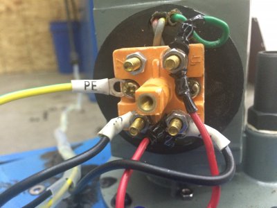
Simple Pump Wiring.... (Well, not simple for me evidently)

Jamespvill

Active User
Registered
Joined
Feb 4, 2014
Messages
185
Gentlemen... I can't seem to figure out how to wire up a coolant pump on my machine, it's a 240....details in the pictures below...
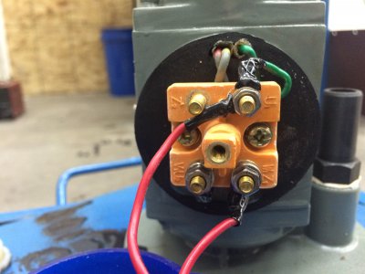
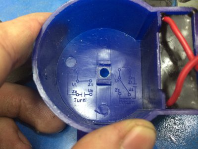
IMG_7403.JPGIMG_7402.JPG

Of course, I've got two black hots and a green neutral to jam into it....just can't seem to figure out where.

One of these days it would probably be beneficial to learn how to read electrical diagrams...

IMG_7402.JPG IMG_7403.JPG
 
To Turn (forward?)


The Hot wires connect to U1, and Z2
U1 is jumped to Z1
The capacitor is connected to Z2 and U2, (the red wires)


To Unturn (reverse?), never seen that term used before.


The Hot wires are connected to U1 and Z1
U1 is jumped to U2
The capacitor is connected Z2 and Z1


In both cases, the green wire (ground) should be connected to the motor frame at some convenient location.

I hope this makes sense.
 
The red wires are the capacitor, and they are already on Z1 & Z2. So if you connect your 240VAC (You have two black leads? Really?) to U1 & Z1, and a jumper between U1 & U2, the motor should "unturn", which as Jim Dawson pointed out, probably means to turn in reverse.....not sure if that woul dbe correct direction for your pump or not.


Is this a used pump? If so, it's very likely the position of the capacitor is correct, and "unturn" is the direction you want it to rotate.....

For reference, the "sine wave" symbol means a power source(your AC line) and the two parallel lines mean a capacitor.


Andy, you might take another look at the labels on the terminal block, the capacitor seems to be connected to U1 and Z1, as I read it.

Thank you for adding the symbol explanation.
 
Thank you for the assistance gentlemen!

I now posses a slightly more advanced knowledge of electrical workings than I had a few hours ago. Unfortunately none of the suggestions worked...


After killing my multimeter (I still don't know how...), Getting a love kiss from the capacitor, and throwing only one item across the room I now have a functioning pump.

Here is how it ended up in "turn" mode; To access "unturn" mode move the left black wire to U1.
IMG_7407.JPG

Don't mind the ground, that has since been properly secured.

Anywho, it appears as though the diagram is wrong or the motor is wired wrong. Regardless, It is dinner time now and I am hungry.

And again, A big thanks for the help folks! I should be showing off the machine that the pump is attached to fairly soon.

IMG_7407.JPG
 
Andy, you might take another look at the labels on the terminal block, the capacitor seems to be connected to U1 and Z1, as I read it.

Thank you for adding the symbol explanation.

Right you are, Jim!

Thanks for spotting my error.
 
Back
Top