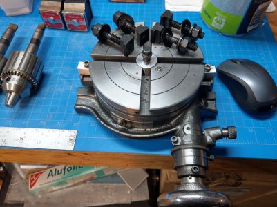
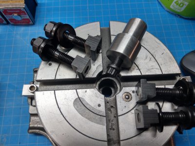
Setup of work piece on rotary table

Just for fun

Tim Young
H-M Lifetime Diamond Member
Joined
Oct 7, 2020
Messages
2,116
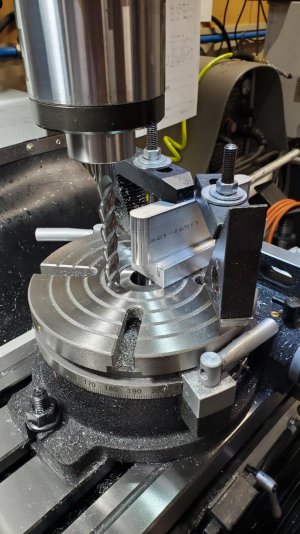
This is only the second time playing with my rotary table. I had the table centered under the quill to start with and locked in the Y axis. I'm sure there are some measurements to setup properly, I just eyeballed the depth, if you will. And took way to long trying to get it centered so I could cut a nice radius, and still didn't have it right. Close but not right. The bar is 19mm thick, I had already removed the part, so I just stuck it in there for the photo, but that is pretty close to how I had it setup.

I have seen bar's clamped to the rotary tables, but I'm not sure how they are used. I know Joe Pie did a video on rotary table setup, and there probably others. I thought I would start here before going to YouTube.
20230308_175634.jpg
 
I have a dead center that fits in the taper of my rotary table. I put a point in my mill and line up the two points. Then I use a Dial in a collet to tune it in the last few thou. If you put a center punch on your piece for the center of the arc, you should be able to put the point back in the collet of your mill and line that point up to your center punch mark. Curious to hear how others would do it. Good luck with your project.
 
The precision of the work is only as good as the setup. RT setups are made easier with fixturing or at least stops and guides to aid in placing the part on the table.

I just pulled some pics I had on hand to demonstrate. I've never been able to just quickly plunk anything on my mill table without some sort of index, RT is no different.

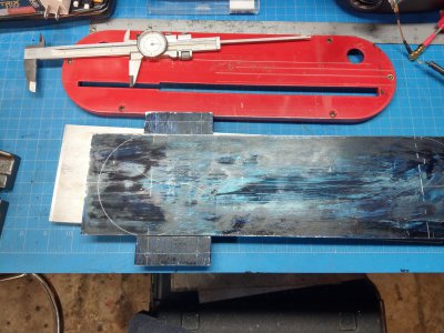
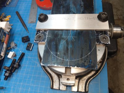
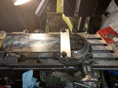
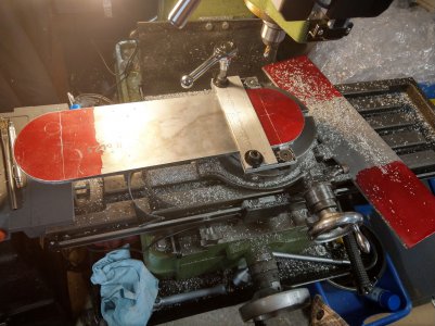
IMAG0159.jpgIMAG0170.jpgIMAG0250 (1).jpgIMAG0254.jpgIMAG0094.jpgIMAG0095.jpg
 
This is only the second time playing with my rotary table. I had the table centered under the quill to start with and locked in the Y axis. I'm sure there are some measurements to setup properly, I just eyeballed the depth, if you will. And took way to long trying to get it centered so I could cut a nice radius, and still didn't have it right. Close but not right. The bar is 19mm thick, I had already removed the part, so I just stuck it in there for the photo, but that is pretty close to how I had it setup.

I have seen bar's clamped to the rotary tables, but I'm not sure how they are used. I know Joe Pie did a video on rotary table setup, and there probably others. I thought I would start here before going to YouTube.

View attachment 440345
Have a look at this video. What you want is an MT spud to go into the hole of the rotary table for centering.
 
Setup on a rotary table to cut arcs can be frustrating, largely because there is no way to control placement of the work.

The first step is to reference the RT to the mill so the axis of the RT is accurately known in the machine coordinate system. I usually set my x and y ordinates to zero on the RT axis. How I proceed from there depends upon the nature of the machining. For any arc tha needs t be cut, I have to place the center of that arc on the RT axis. I also have to accurately know the start and end positions of the arc. This would entail a good deal of trail and error which would entail locating features in x, y, and angular dimension on the table, achieving by loosening the part and tapping into position.

Many DRO's have the ability to cut arcs using a series of connected steps to go from one point on the arc to another point. The accuracy of the cut is related to the size of the step increments If the increments are on the order of a few thousandths, you can actually cut a surface the matches the intended arc very well but this is a tedious process.

Two decades ago, I realized that it was possible to break up any complex curve into a series of connected tangent arcs. If arcs are used rather the steps in x and y, the size of the increments can be much larger. Thus is actually a strategy used in CNC milling for cutting such curves. The problem though, is easily and accurately moving the work to a new coordinate system in the RT so the arc center now located at the center of the arc. If an RT had an x y table on top of it. it would be fairly easy to accomplish this task. Although it would require a fair amount of "bookkeeping" discipline to keep things straight.

I had a project that required cutting a series of curves. My problem was finding a low profile x y table that I could mount on my RT. I have a 12" RT on an RF30 mill which greatly reduced my z axis travel. The maximum distance from the spindle nose to the table is 17". Placing the RT on top reduces that distance to 13". Adding an x y table would reduce the working space to something like 9". By the time the R8 collet and tool holding is added, there is very little remaining for work.
 
Thanks David, I have watched that video in the past and your right I do need something like that.

I do realize I need some sort of fixture but I just can't wrap my head around how to do with this part. Since it's 44mm tall and I want to round the end. Would I still lock the rotary table in the center? I guess I needed to rough it out first?

The way I did it is, I first centered the rotary table under the spindle. I then locked the Y axis and moved the X axis and I took smaller cuts and fed in with the X axis until I got what you see in the photo.

Somehow I needed to square the part up to the X axis, and make it repeatable so I could do the other side.

I kind of did what RJ said. And tapped in into center it was tedious.

Bud's idea with the center punch would have helped. Even a scribe line would have been better than nothing.

Definitely a learning experience.
 
In this particular case, I would set the center of the RT to zero on the mill table and the RT to zero degrees. It would be useful to have a jig piece turned to fit the RT center with a neck equal in radius to the desired arc radius to act as a pivot for the bar.Then I would position a straight edge so it contacted the neck of the jig. This puts the straight edge at a distance half the thickness of the part from the center of rotation. I would adjust the RT so the straight edge was parallel to the x axis and note the angle of the RT. This would give me my angular correction. I would next mount a short block perpendicular to the first and in contact with my jig neck. This defines the end of the part. Now, remove the jig and place the part in contact with both straight edge guides and clamp in place. Set the x axis to zero and the y axis to the sum of the radius of the cut plus the radius of the cutter. The actual cut would start at the RT angle reading less 90º and end at 90º.
 
Thanks RJ, I'll have to read that a couple of times too get handle on you just said. I'll give it a try.
 
Joe Pie keeps a bar bolted to his RT that is a known distance from center. He uses an adjustable parallel or filler block to set the work to the correct position. Check out his YouTube videos.

I just watched (again) his video from bout 3 yr ago. It showed how he used stops and shims to orient his parts.
 
Last edited:
Thanks David, I have watched that video in the past and your right I do need something like that.

I do realize I need some sort of fixture but I just can't wrap my head around how to do with this part. Since it's 44mm tall and I want to round the end. Would I still lock the rotary table in the center? I guess I needed to rough it out first?

The way I did it is, I first centered the rotary table under the spindle. I then locked the Y axis and moved the X axis and I took smaller cuts and fed in with the X axis until I got what you see in the photo.

Somehow I needed to square the part up to the X axis, and make it repeatable so I could do the other side.

I kind of did what RJ said. And tapped in into center it was tedious.

Bud's idea with the center punch would have helped. Even a scribe line would have been better than nothing.

Definitely a learning experience.
On my rotary table it can stand on its end so it has a flat edge. It looks like yours does as well. I use a machinist square when I first bolt my rotary to the mill table to get that edge line up with my X and Y. Then after you center the rotary under your quill, dial etc. Put the point in your mill collet. Mark the center of your ark with a center punch. Put your piece on the rotary table, put the point in your center punch mark and use the machinist square to align your part perpendicular to the flat base on your rotary. This should put your part aligned with the x axis on your mill. Bolt it down. Offset your X the radius of your arc plus half the cutter diameter and you should be able to make your cut. Go further for your rough cuts and finish at that final radius. Should be pretty repeatable. I am just visualizing this so may have missed a step but I think that should get you what you want.
 
Back
Top