Servo VFD direct drive conversion.

akjeff

H-M Supporter - Gold Member
H-M Supporter Gold Member
Joined
Aug 21, 2020
Messages
692
Finally got all the pieces/parts in hand to complete the head rebuild of my Lagun FTV-1, with the Servo VFD conversion( https://www.servoproductsco.com/specs/servo_vfd.pdf ) being the last piece of the puzzle. For the backstory on why the rebuild and what it entailed, here's a link to the rebuild up until it veers off to the VFD conversion detailed in this thread. https://www.hobby-machinist.com/threads/ftv-1-head-rebuild.98269/

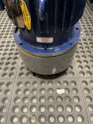
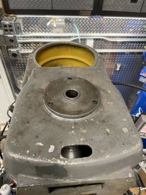
The 5hp motor was the last part to arrive, and when I opened the box thought "oh no, this thing is never going to fit ", as it dwarfed the factory 3hp. But after a test fit on the drive cover casting, was relieved to see that it fit perfectly. At about 110 pounds, it's a beast.
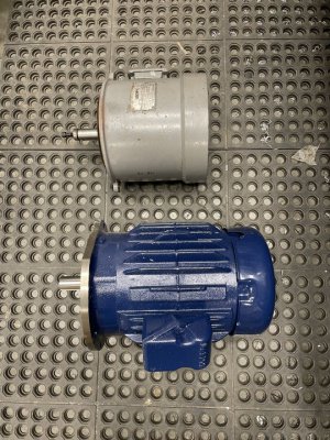
IMG_9822.JPG

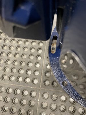
Hole spacing was spot on, to my great relief.
IMG_9815.JPG
IMG_9816.JPG
IMG_9814.JPG

This install will be spread out over several posts, as time allows.
 
Last edited:
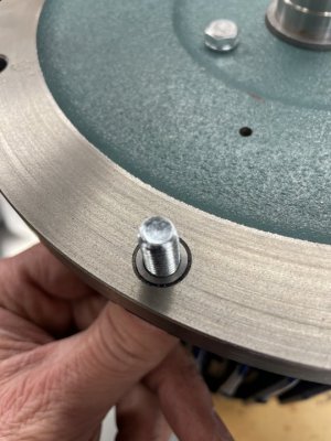
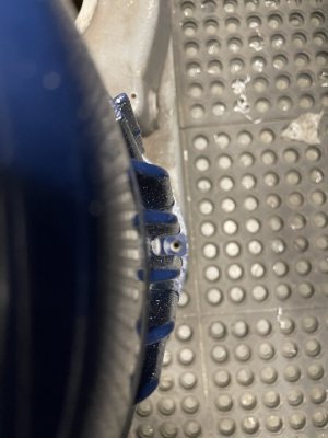
The bolt holes on the motor flange, had an I.D. of just over 11mm. The mounting bolts on my Lagun are M8, so I made a bushing to insure the bolt/hole that acts as the pivot point was a good slop free fit.
IMG_9823.JPG

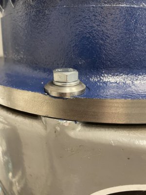
I was also concerned that using a simple flat washer under the bolt head, may cause it to "taco" on the one spanning the slotted hole. So, a pair of 4mm thick washers was made out of 4140, to provide good clamping force without deforming.
IMG_9831.JPG

This all needed to be sorted out before bolting the belt cover casting to the mill, as I only wanted to mount the motor once! Test fitting is much easier safely on the shop floor!
 
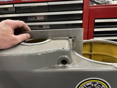
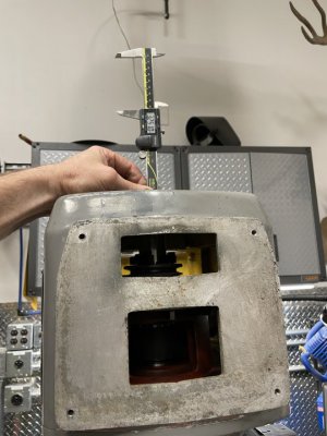
A very critical reference measurement needs to be taken, and it's easiest to do while the cover casting is on the bench. This is to record the height difference between the machined surfaces of the spindle bearing cap, and the motor mount flange. I cantilevered a straight edge off the bearing cap surface, and then used Jo-blocks to arrive at a difference of 1.750" in this case. This dimension will be needed later on to properly locate the pulley on the motor shaft.
IMG_9818.JPG
 
I assume you are going to go with a single pulley drive with a direct drive to the spindle. The Super E-motor should be good for 120Hz possibly a bit more. Vector motors I usually spin from 20-200 Hz, the wider speed range one can usually get by with a single speed pulley drive. Since you have a 5 Hp motor, you can make up for some of the low speed power loss.
 
I assume you are going to go with a single pulley drive with a direct drive to the spindle. The Super E-motor should be good for 120Hz possibly a bit more. Vector motors I usually spin from 20-200 Hz, the wider speed range one can usually get by with a single speed pulley drive. Since you have a 5 Hp motor, you can make up for some of the low speed power loss.
Correct, it's the whole package from Servo. 1:1 pulleys. 50-500rpm in back gear, and 500-5000rpm in direct drive. I went with a 5hp over the 3hp for the reason you mentioned.
 
A very critical reference measurement needs to be taken, and it's easiest to do while the cover casting is on the bench. This is to record the height difference between the machined surfaces of the spindle bearing cap, and the motor mount flange. I cantilevered a straight edge off the bearing cap surface, and then used Jo-blocks to arrive at a difference of 1.750" in this case. This dimension will be needed later on to properly locate the pulley on the motor shaft.
View attachment 403842
Love the Bultaco sticker.. a Matador 250 is what i learned on!
 
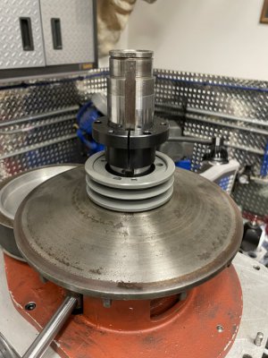
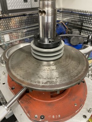
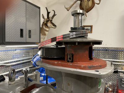
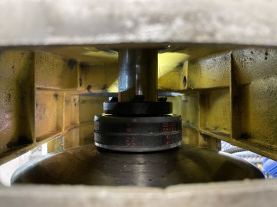
Now that the reference dimension has been recorded, work can begin putting it all together. Remove the moving disc of the factory variable drive, and install the spindle pulley. It is secured to the shaft via a wedge lock. I just bottomed out the pulley on the top of the fixed disc/brake drum, and tighten it down. Then the top bearing can be installed, and the the assembly is slid over the spindle and seated into place. Finally, the belts are slipped over the spindle, as once the cover casting goes on, they'll be trapped there for good.
IMG_9774.JPG
IMG_9777.JPG
IMG_9819.JPG
 
With the belts in place, it's time to install the cover casting. With it tightened down, another reference measurement needs to be taken. This is the distance from the same machined surface of the bearing cap mounting flange, down to the top of the pulley on the spindle shaft. Record this value, as it will be needed in a few steps. Once you have the dimension recorded, you can install the top bearing cap on the bearing/cover.
IMG_9820.JPG
IMG_9821.JPG
 
Last edited:
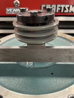
Now that the two reference measurements have been taken, the difference between them will determine the gap between the face of the motor flange, and the top of the pulley. I used a straight edge and Jo-blocks to stack up to the proper height to locate the pulley. Bear in mind that when you tighten up the wedge lock pulley, it will draw the pulley up once the inner hub tightens up on the motor shaft. So, you'll have to experiment with the pulley to skew your placement, so that it pulls it to the desired gap. I needed to fudge mine about -.015". If you tighten up the wedge lock and need to loosen it to reposition, do not try to pry/ hammer it apart......use the jack bolt threaded holes and follow the directions.
IMG_9824.JPG
 
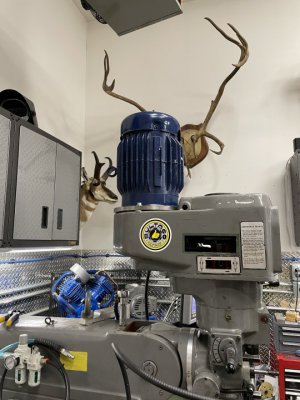
Now that the pulleys are properly located, the real fun begins; starting with wrestling the 110 pound motor on to the head of the mill! I managed to haul it up the step ladder and mount it without assistance, but it wasn't a good idea. There's a lift eye on the motor for a reason! Put the mounting bolts in and snug up the "pivot bolt", but still allow the motor to be adjusted. Push it forward as far as it will go, which leads us to the second fun part of the install......getting the belts on the pulleys.
IMG_9828.JPG

If you don't use profanity, there's a good chance you will start when you put the belts on the pulleys! There's not a hell of a lot of room to get your hands in there, and I found it to be a bit maddening. Just keep at it, and get it done. Here's what it looks like when they're in place. Sorry for the crappy focus on the first photo.
IMG_9825.JPG
IMG_9827.JPG

Time to move on the electrical/control installation.
 
Back
Top