Scribe a perpendicular line around fillets on a square steel tube

Seems like the solution in post #10 would work fine, if I'm understanding your need correctly.

How long are the finished pieces? Could you put them in a mill vise and side mill them?

How perpendicular do these need to be, anyway?
 
If that were me doing that, I'd more than likely jump to one of a couple of solutions that are NOT PERFECT, but probably near enough to perfect that they'll be more accurate than "non machine tool" end squaring.

Option one, depending on how much radius this tube has, I'd probably take a shot at the speed square. Laying the "wide" edge against the radius, you can scribe one side, and the other side can be "marked for subsequent scribing" at the wide side of said speed square. Then when the square is moved to that side.... You line up to that mark.

Option two, if the radius is wider than the speed square will work with, Two inch masking tape or painters tape. Wrap it around with reasonable (not excessive) care to keep it straight. No wrinkles allowed, just keep the tension even as you lay it down so you don't impart a curve. When you come around and the ends line up, you know you've got it. If you missed... Peel it back and adjust it about yay much. It seldom takes more than a couple of shots at it. Then use that to line up a square for scribing, or depending how you're getting the cutting done, use the tape as the scribe.
 
Seems like the solution in post #10 would work fine, if I'm understanding your need correctly.

How long are the finished pieces? Could you put them in a mill vise and side mill them?

How perpendicular do these need to be, anyway?

I'm building a PrintNC. These are for the X and Y nut housing for the lead screws.

I'd have to export the STL files to confirm this, but I /think/ they get their squareness not so much from the flat face that will go up against these ends, but from the fit of the insert into steel tube.

So, it's kind of like the bushing not the flange. So, the tolerances probably don't matter too much. If I had a mill, milling them flat would be more than good enough. Anyway, I look at all of this as a learning and skill building opportunity, so getting these tips has been fantastic.
As soon as you said 3x2 tubing I thought, "bet he's building a PrintNC router"...
You want the cuts to be a square as possible but it is possible to shim the ball nuts after the fact. :)
 
If that were me doing that, I'd more than likely jump to one of a couple of solutions that are NOT PERFECT, but probably near enough to perfect that they'll be more accurate than "non machine tool" end squaring.

Option one, depending on how much radius this tube has, I'd probably take a shot at the speed square. Laying the "wide" edge against the radius, you can scribe one side, and the other side can be "marked for subsequent scribing" at the wide side of said speed square. Then when the square is moved to that side.... You line up to that mark.

Option two, if the radius is wider than the speed square will work with, Two inch masking tape or painters tape. Wrap it around with reasonable (not excessive) care to keep it straight. No wrinkles allowed, just keep the tension even as you lay it down so you don't impart a curve. When you come around and the ends line up, you know you've got it. If you missed... Peel it back and adjust it about yay much. It seldom takes more than a couple of shots at it. Then use that to line up a square for scribing, or depending how you're getting the cutting done, use the tape as the scribe.

As soon as you said 3x2 tubing I thought, "bet he's building a PrintNC router"...
You want the cuts to be a square as possible but it is possible to shim the ball nuts after the fact. :)
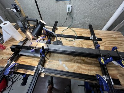
I've been obsessing about accuracy. More so than I probably should, according to the Discord convos I've had. For example, To cut the long beams, I built this sled on linear rails jig.IMG_5947.jpeg
As is always the case, it would be a lot easier to build a PrintNC if I already had an even more capable setup than a PrintNC, like a mill :)
 
I have rough cut 3x2 rectangular structural steel tubes to slightly longer than my desired length.

I would like to scribe a line as a guide to grind, file and sand them down such that the ends are as near as 90 degrees to the length as I can manage.

Using a machinists t-square works fine for the first face, but obviously it can’t follow the fillet onto the next face. Of course, I can’t measure from the bottom of the next face because they aren’t square and that’s the whole reason I’m doing this :)

My solution was to 3D print a sleeve that I can use as a guide for the scribe. I’ve attached a screen snap of the CAD drawing for the curious.

My question is: Is there another (better?) way to do this? My machinist grandfather wouldn’t have had a 3D printer, though he - unlike me - had a Bridgeport which could do the job. What might he have done if he didn’t have a Bridgeport and only had hand tools?

Thanks!
With hand tools my grandfather would have used a square, a scribe, a hack saw and a file. With the square scribe a line around the steel, clamp it in a vice and do his best to stay to the waste side of the line. Then using the square again, this time across the cut, file the cut edges until the square sets on both opposite sides and measured from all 4 sides. Perfect only comes from God. We can only come close.
 
Back
Top