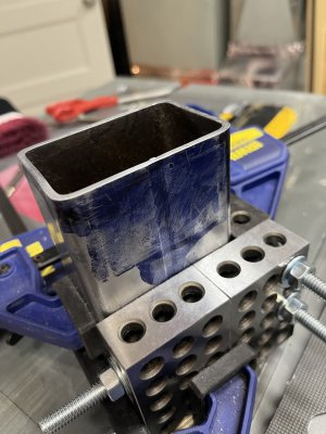
Scribe a perpendicular line around fillets on a square steel tube

A postscript for anyone who stumbles upon this later:

After I scribed the line around the tubes, I tried a few different ways of cutting them to make them as close to square as I could without a mill. I had reasonable results using a 2HP belt sander I made for knife making and a file. I got the best results like this:

While I don’t have a mill, I do have a router table. I put a carbide end mill into the router, use machinist squares to align a guide, and make the shallowest cuts I can set up.

I’ve clamped123 blocks to the piece and slide them, not the piece, along the guide. They’re square, the piece is not (yet), so using them to square up and having a small gap between the piece and the guide should result in a more square cut.

Obviously, a mill would be stiffer, but this is the best I think I can manage with the tools I have, and for the PrintNC, this should be within spec.
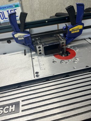
IMG_5983.jpeg
 
That seems really sketchy to me! Those clamps can vibrate loose and they don't really have much gripping force anyway. I may have missed it but why do these need to be so perfectly square?
 
That seems really sketchy to me! Those clamps can vibrate loose and they don't really have much gripping force anyway. I may have missed it but why do these need to be so perfectly square?
I came to the conclusion that I should do it slightly differently, for different reasons, but the result of which, I think, will address your concerns of sketchiness:

I want to make cuts that are less than a sheet of paper's thickness, which is less than four thou. The guide isn't easy to adjust, so I'm planning on using 8020 aluminum extrusions as a guide. I can more easily adjust them and secure them more thoroughly, so I think that will do the trick.

I didn't say why I'm trying for the best tolerances I can manage in the initial post, and only mentioned it in response to another comment so, in answer of your question:

I'm building a PrintNC CNC router. Since it's a router, not a mill, it should be good for about four thou tolerance at best. Not "machining" per se, but useful for the projects I have in mind.

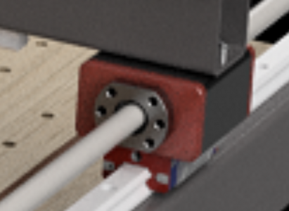
The photo I've attached shows how you attach the lead screws. The red lead screw nut holders in the photo slide into the tube. They're 3D printed plastic to begin with, and later replaced with aluminum. If the tube is not square, the nut holder won't be true, because it gets its orientation, at least partially from the front face. You can shim it, and I plan to print them "deep" so that they get some of their orientation from the sleeve of the tube, but it'll be more straightforward with more square cuts.

Screenshot 2023-10-20 at 8.12.37 PM.png
 
As a second postscript for this thread, I want to say, “Thanks!” So many people here, and in related threads, shared their experiences. I’m grateful.

Here is a photo of the end result. Acknowledging the limits of a piece of glass for a reference surface, measuring with a dial indicator it is flat to about 5 thousandths, which meets (and almost certainly exceeds) the spec for the project.

The process I followed was:

(1) Scribed a line all the way around the tube using 3d printed sleeve as a guide. Verified with machinist’s t-square.

(2) Cut with portable bandsaw in vise table saw.

(3) Did the questionable router table thing as above. I’m of two minds about whether to do this for the other two I will do. Making a series of cuts 1/8” tall by a few hundredths thickness, lowering the piece each cut to cut the next 1/8th inch, guided by a rail made of aluminum extrusions clamped square to the table, de-burring between cuts worked. However, it felt perilous and was only just repeatable. I may skip this for the next two and do it all with files.

^^^ Later edit: This was a bad idea that nearly got me hurt. Don’t.

(4) Clamp piece square in an L shaped 1-2-3 form. Form flatness verified with dial indicator beforehand, L verified 90 degrees with t-square. The piece does not touch at the bottom, since the bottom isn’t square. Thank you “That Lazy Machinist” for your isostatic positioning YouTube video.

(5) Slide 1-2-3 form/piece around reference surface under dial indicator. Find and file high spots. Eventually, sand high spots.

This took a long time, about which I am not all bothered. It was very satisfying. Best tolerance I’ve ever been able to achieve within the limits of my shop as it’s currently equipped.

IMG_6016.jpeg

 
Last edited:
For anyone reading this in the future: using a router table with a carbide die grinder bit on steel is a bad idea. It’s dangerous in the way a table saw is in that it can grab the work piece. I scared myself pretty badly, but fortunately wasn’t hurt.
 
For anyone reading this in the future: using a router table with a carbide die grinder bit on steel is a bad idea. It’s dangerous in the way a table saw is in that it can grab the work piece. I scared myself pretty badly, but fortunately wasn’t hurt.
Glad you are ok. You can do very slight round overs or chamfers, but very little at a time, and you must be prepared to understand what it will do.
some have made chamfer tools from routers. I would never use a flush trim or straight bit.
 
Back
Top