Pinresto (Please sign all posts with your real name),
First, lets sort out your switch. Shown below is what is (according to Internet sources) the switching diagram of your C-H switch, but as I have less than total trust in anything found on the Internet, lets first confirm this. You will need either an ohmmeter or at least a continuity tester, which can be something as simple as a battery in series with a lamp rated for the battery voltage, and two wire leads coming off of the battery in series with the lamp.
Ignore the three terminals (screws) running from top to bottom of the switch's terminal board as they do not seem to have anything connected to them. Also ignore the L1, L1 and 4 stickers on your switch. The left three terminals, from top (the end with the handle) to bottom are 1, 3, 5. The right three are 2, 4, 6. With the switch in the OFF (center) position confirm that no terminal is connected electrically to any other terminal. Move the switch lever to the left and confirm that 1 connects to 2, 3 connects to 4, and 5 connects to 6. Move the switch to the right position and confirm that 1 still connects to 2, but that 3 now connects to 5 and 4 now connects to 6. If that all checks out, then the diagram is correct for your switch.
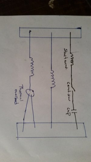
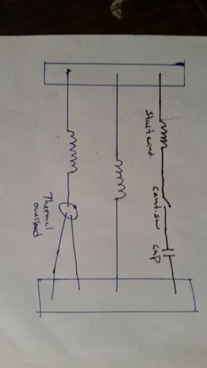
It is also correct for your motor so long as you realize that the only difference between a split phase motor hookup and a capacitor start motor hookup is that in series with the start winding is the start capacitor in series with the centrifugal switch. And that it makes no difference in which order the start winding, switch and capacitor are connected so long as they are all three in series, not in parallel.
Now to your motor. 7 wires cannot work. There should be either 6 or 8. You will have to take it back apart and figure out where you went wrong.
There should be two wires for the START winding. It doesn't much matter which is START and which is FINISH as if the motor starts backwards you can always fix it by swapping the two wires on the switch. One of the wires probably goes to one end of the start winding and the other to either the switch or the capacitor. But it would work just as well if one went to the switch and the other to the capacitor so long as the other side of the switch and the other side of the capacitor each went to one end of the winding (not both to the same end, of course).
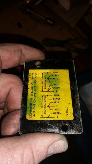
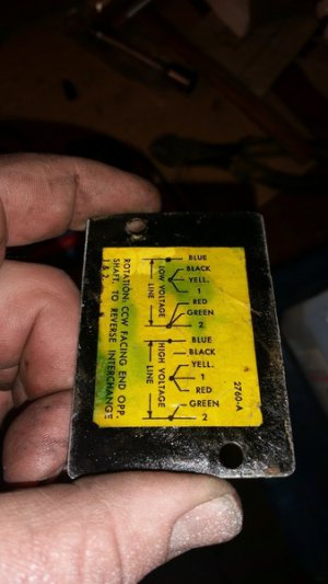
There should be two wires going to the first RUN winding and two more going to the second RUN winding. Furthermore, you need to know which of each pair of wires is START and which is FINISH of their respective windings. If you have lost that information, determining which is which is most likely beyond your capability because of lack of the necessary test equipment if for no other reason. So you will have to determine it by cut and try. However, if you can see where the wires go into the coils, if one is obviously on the side of the coil nearest the armature and the other clearly on the outside, then the first is probably START and the second FINISH. In the attached diagrams, T1 and T2 are START and T3 and T4 are FINISH. If you can't determine which is which, then all that you can do is wire it up at random, plug it into a fused circuit with no larger than a 15 amp fuse or circuit breaker, and turn it on. If it immediately starts, you guessed right (even if it runs backwards - that is another guess). If it hums loudly and doesn't immediately spin up to speed, turn it back off immediately. Unplug the motor and swap the two wires from only ONE winding, not both. And try it again. Then, if it runs backwards, stop it, unplug it, and swap the two start winding wires.
Finally, the 7th wire. Presumably, this goes to the thermal/overload circuit breaker mounted in the motor. There are actually two terminals on a thermal breaker. Either you failed to bring out an 8th wire for the other side of that breaker, or the other side is connected to one of the four run winding wires. What to do depends upon which case you find and whether you are connecting it for 120V or 240V. Rather that writing four fixes, I am going to wait for you to investigate and see what you find and which voltage you are hooking it up for. But I will say that the thermal breaker should be in series with the run windings whether they are paralled for 120 V or seriesed for 240V.
 [/URL]
 [/URL]
